
Installation Guide


-6-
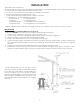
Equivalent Vent Length (EVL)
The longer the run of pipe in your installation (both with inserts and freestandings), the more restriction there is in
the system. Therefore, larger diameter pipe should be used.
• Use 4” pipe if you have more than 15 feet of equivalent vent length.
• Horizontal runs shall not exceed 10 feet of EVL.
• It is recommended that vertical runs be a minimum of 8 feet.
• To calculate EVL, use the following conversions:
90º elbow or “T” = 5 equivalent feet
45º elbow = 3 equivalent feet
Horizontal Pipe Run = 1 equivalent foot per actual foot
Vertical Pipe Run = 0.5 equivalent foot per actual foot
NOTE: At altitudes above 3,000 feet, we suggest the use of 4” diameter vent at an EVL of 7 feet or more.
INSTALLATION
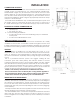
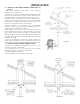
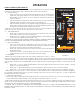
A. HORIZONTALLY THROUGH WALL (refer to Figure 6)
NOTE: See “VENTING” and follow L-Vent chimney manufacturer’s instructions.
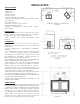
1. Position stove, adhering to clearances shown in Figures 1 & 2.
2. Locate position of hole in wall; directly behind stove exhaust vent (refer to gure 4).
3. Always maintain 3” clearance from combustible materials.
4. Install L-Vent wall thimble per L-Vent manufacturer’s instructions.
5. Attach enough piping to penetrate and extend at least 6” beyond exterior walls. An 8-foot vertical pipe
run is suggested where possible to reduce the possibility of smoke spill age in the event of a loss of negative
pressure.
6. Attach cap and seal outside wall thimbles with non-hardening waterproof mastic.
7. Termination should not be located so that hot exhaust gases can ignite trees, shrubs, or grasses or be a
hazard to children. Exhaust gases can reach temperatures of 500ºF and cause serious burns if touched.
Locate terminations: a) not less than 3 feet
above any forced air inlet located within 10 feet;
b) not less than 4 feet below or horizontally from,
or one foot above, any door, window or gravity
air inlet into any building; c) not less than two feet
from an adjacent building and not less than 7 feet
above grade when located adjacent to a public
walkway.
INSTALLATION
FIGURE 6