
Installation Guide

© 2021 United States Stove Company
7
ATTENTION:
DO NOT VENT UNDER ANY PORCH, DECK,
AWNING, OR IN ANY SEMI ENCLOSED OR
ROOFED AREA. DOING SO MAY RESULT IN
UNPREDICTABLE AIRFLOW AT THE VENT
CAP UNDER CERTAIN CONDITIONS AND CAN
AFFECT THE PERFORMANCE OF YOUR STOVE,
AS WELL AS, OTHER UNFORESEEABLE ISSUES.
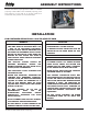
WALL INSTALLATION
Select a wall to the exterior of the building. This wall
should have the required clearance to combustibles
inside and out as mentioned in this manual. Make
certain that electrical wires, conduit, water or
gas pipes do not pass through the area you have
selected.
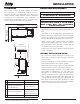
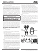
5/8”
[16mm]
16”
[406mm]
3”
[75mm]
A. Step 1 - Mount the wall plate
Note: Any material covering the wall (such as sheet
rock) must not exceed 5/8” (16 mm).
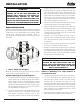
Option 1: Mounting on a wood-stud wall
1. Locate the studs in exterior wall. Verify the center
of the stud with an edge-to-edge stud nder.
Mark center point at predetermined height
which meets all clearance requirements of the
appliance. Note: Make sure that the opening for
the exhaust thimble is not to close to a stud in
the wall before the hole is cut.
2. At the wall height that was determined in the
previous step, place a mid-sized nail through
the center triangular shaped hole of the
mounting plate to hold it while the locations
of the mounting holes and the exhaust/intake
through hole are marked. Make sure that the
wall mounting plate is ush against the wall,
then level the mounting plate and verify that
pilot holes are centered properly on the studs.
Use a pencil to mark the pilot hole locations,
and intake/ exhaust through hole, then remove
the mounting plate from the wall.
3. Drill the four pilot holes to a depth of 2” (75 mm)
using a 5/32” (3.96 mm) diameter drill bit.
4. Find the center of the through hole for the wall
thimble and drill a pilot hole all the way through
the wall to the exterior with an installer bit.
Use this hole as a center point to cut your hole
through the exterior wall.
5. Carefully cut exhaust/intake through hole in
exterior wall completely through to the outside
(see “Vent Clearances” section to ensure proper
installation).
6. Install the wall thimble included with the vent
kit to the manufactures instructions.
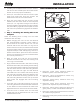
7. Realign the wall mount with the pilot holes and
exhaust/intake through hole. Insert the four 1/4”
x 2” lag bolts with washers, and tighten the lag
bolts until the wall mounting bracket is pulled
rmly against the exterior wall.
WARNING:
AVOID POTENTIAL INJURIES OR PROPERTY
DAMAGE! DO NOT OVER-TIGHTEN THE LAG
BOLTS. THIS COULD POTENTIALLY STRIP THE
MOUNTING HOLES AND CAUSE THE BOLTS
NOT TO HOLD CORRECTLY.
Option 2: Mounting on a solid concrete or
concrete block wall
1. Level the wall plate and mark the hole locations.
2. At the wall height you determined in the
previous step, place a small nail thru center
triangle hole of bracket and align the wall
mount against the wall. Level bracket and verify
that pilot holes are not located in the mortar of
the cinder blocks. Use a pencil to mark the pilot
hole locations, and intake/exhaust thru hole
then remove the wall plate.
3. Drill pilot holes to a depth of 2” (75 mm) using a
5/32” (3.96 mm) diameter masonry drill bit.
INSTALLATION