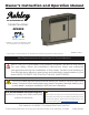
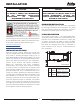
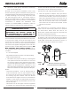
Owner’s Instruction and Operation Manual Model Number: AP5000 R Report #: F20-598 Certified to ASTM Std E1509-12 (2017) and Certified to ULC-S627-00-REV1 * All Pictures In This Manual Are For Illustrative Purposes Only. Actual Product May Vary. 853627C-2502J Save These Instructions In A Safe Place For Future Reference. SAFETY NOTICE: If this heater is not properly installed, a house fire may result. For your safety, follow the installation instructions.
INTRODUCTION This manual describes the installation and operation of the Ashley, AP5000 wood heater. This heater meets the 2020 U.S. Environmental protection agency’s crib wood emission limits for wood heaters sold after may 15, 2020. Under specific test conditions this heater has been shown to deliver heat at rates ranging from 8,141 to 12,161 btu/hr output. Heating Specifications Heating Capacity 500 - 1,000 sq. ft. Fuel Burn Rate 3/4 - 2 1/2 lbs. /hr.
INSTALLATION CHECKLIST Your Wood Stove should be installed by a qualified installer only. An NFI qualified Installer can be found at www.nficertified.org/public/find-an-nfi-pro/ CUSTOMER SERVICE 1-800-750-2723 ext 5050 Text to 423-301-5624 Email to: Customerservice@usstove.com COMMISSIONING CHECKLIST This Checklist is to be completed in full by the qualified person who installs this unit. Keep this page for future reference.
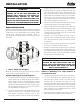
ASSEMBLY INSTRUCTIONS Ensure the flame impingement baffle is installed properly. If the baffle is not installed properly, push the plate up in the void at an angle, rotate it to horizontal and place it on the metal stops. Flame Impingement Baffle INSTALLATION FOR CUSTOMER SERVICE CALL: 800-750-2723 EXT 5050 WARNING: ATTENTION: • A POWER SURGE PROTECTOR IS REQUIRED. THIS UNIT MUST BE PLUGGED INTO A 110 - 120V, 60 HZ GROUNDED ELECTRICAL OUTLET. DO NOT USE AN ADAPTER PLUG OR SEVER THE GROUNDING PLUG.
INSTALLATION CAUTION: CAUTION: CONTACT YOUR LOCAL BUILDING OFFICIALS TO OBTAIN A PERMIT AND INFORMATION ON ANY ADDITIONAL INSTALLATION RESTRICTIONS OR INSPECTION REQUIREMENTS IN YOUR AREA. BEFORE INSTALLING YOUR HEATER, YOU MUST PERFORM AN INITIAL BURN IN AN OUTSIDE ENVIRONMENT. FOLLOW THE START-UP PROCEDURE IN THE OPERATION SECTION OF THIS MANUAL. IMPROPER INSTALLATION The manufacturer will not be held responsible for damage caused by the malfunction of a stove due to improper venting or installation.
INSTALLATION CLEARANCES Your pellet stove has been tested and listed for installation in residential, mobile home in accordance with the clearances given below. For safety reasons, please adhere to the installation clearances and restrictions. Any reduction in clearance to combustibles may only be done by means approved by a regulatory authority.
INSTALLATION of the mounting holes and the exhaust/intake through hole are marked. Make sure that the wall mounting plate is flush against the wall, then level the mounting plate and verify that pilot holes are centered properly on the studs. Use a pencil to mark the pilot hole locations, and intake/ exhaust through hole, then remove the mounting plate from the wall. ATTENTION: DO NOT VENT UNDER ANY PORCH, DECK, AWNING, OR IN ANY SEMI ENCLOSED OR ROOFED AREA.
INSTALLATION 4. Carefully cut intake/exhaust thru hole in exterior wall thru to the outside (see “Vent Clearances” section to ensure proper installation). 5. VENT TERMINATION CLEARANCES Insert 1/4” concrete wall anchors into the pilot holes and make sure that the anchors are seated flush with the concrete surface. 6. Align the wall plate with the anchors.
INSTALLATION H. Minimum 1-foot [0.3m] clearance horizontally from combustible wall. NOTICE: This unit shall be installed in such a way that the exhaust gases are directed so they do not jeopardize people, overheat combustible structures, or enter buildings. The chimney connector shall not pass through an attic or roof space, closet or similar concealed space, or a floor, or ceiling.
OPERATION INSTRUCTIONS NEVER OPERATE THIS PRODUCT WHILE UNATTENDED HOW YOUR HEATER WORKS Your pellet heater operates on a timer based auger fuel feed system, that is controlled by a digital circuit board. The fuel is delivered from the auger into a burn pot, which is the vessel where the combustion process takes place. Based upon the heat ranges (1-5), the heater will feed the appropriate amount of fuel to reach a set temperature range.
OPERATION INSTRUCTIONS 6. Materials containing asbestos; 7. of smoke or fumes irradiating from the appliance during this process. Follow the Start-Up procedure below to begin your burn. Construction or demolition debris; 8. Railroad ties or pressure-treated wood; START-UP PROCEDURE 9. Manure or animal remains; 10. Salt water driftwood or other previously salt water saturated materials; 11. Unseasoned wood; or 12. Paper products, cardboard, plywood, or particleboard.
OPERATION INSTRUCTIONS The heater will begin to feed fuel and the exhaust (draft) blower is running. Note that the exhaust blower is pulsing. The auto-start ignitor will ignite the fuel in approximately 5-10 minutes. In the startup mode, the “ON” LED will flash until it reaches a factory preset temperature. At that point, the “ON” LED will come on solid and the heater will begin to ramp up to your selected heat range.
MAINTENANCE NEVER OPERATE THIS PRODUCT WHILE UNATTENDED your heater, we suggest using a vacuum designed for ash removal. Some regular vacuum cleaner (i.e. shop vacs) may leak ash into the room. WARNING: • DISCONNECT THE POWER CORD BEFORE PERFORMING ANY MAINTENANCE! NOTE: TURNING THE ON/OFF SWITCH TO ”OFF” DOES NOT DISCONNECT ALL POWER TO THE ELECTRICAL COMPONENTS OF THE HEATER. ASH REMOVAL Remove the ashes periodically to avoid unnecessary ash build up.
MAINTENANCE SMOKE AND CO MONITORS Burning wood naturally produces smoke and carbon monoxide(CO) emissions. CO is a poisonous gas when exposed to elevated concentrations for extended periods of time. While the modern combustion systems in heaters drastically reduce the amount of CO emitted out the chimney, exposure to the gases in closed or confined areas can be dangerous. Make sure your stove gaskets and chimney joints are in good working order and sealing properly to ensure unintended exposure.
MAINTENANCE YEARLY SERVICING A yearly servicing and cleaning by your Authorized pellet heater dealer is recommended. A fee may be charged for this service. Burn Pot MAINTENANCE SCHEDULE Combustion Chamber Use the following as a guide under average use conditions. Daily Weekly Stirred Empty Monthly or as needed Brushed Ashes Check Empty Gaskets around door and door glass should be inspected and repaired or replaced when necessary.
TROUBLE SHOOTING ERRORS • Disconnect the power cord before performing any maintenance! NOTE: Switching the appliance to ”OFF” does not disconnect all power to the electrical components of the heater. • Never try to repair or replace any part of the heater unless instructions for doing so are given in this manual or supplied from the factory. All other work should be done by a trained technician. PROBLEM CAUSE: To rich air/fuel mixture Clean out the burn pot and behind the cleanout door.
TROUBLE SHOOTING ERRORS The firebox is not properly Make sure the door is closed and that the gasket is in good shape. sealed. Vent pipe is incorrectly installed Check to make sure vent pipe installation meets criteria in owner’s manual. The pressure switch connections are bad. Check the connectors that attach the wires to the pressure switch. Combustion blower failure. wire With the stove on, check to see if the combustion blower is running.
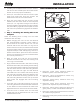
WIRING DIAGRAM Ensure the wires are connected to the bottom two prongs of the hopper switch as shown. CORRECT WRONG HOW TO ORDER REPAIR PARTS For Parts Assistance Call: 800-750-2723 Ext 5051 or Email: parts@usstove.com The information in this owner’s manual is specific to your unit. When ordering replacement parts the information in this manual will help to ensure the correct items are ordered. Before contacting customer service write down the model number and the serial number of this unit.
18 15 21 16 19 20 1 17 14 13 19 12 10 11 22 23 9 24 8 5 3 4 25 7 6 2 30 29 26 28 27 31 33 32 34 REPAIR PARTS © 2021 United States Stove Company
REPAIR PARTS Key Part # Description Qty 1 893318 Distribution Fan Enclosure Panel 1 2 893319 Distribution Fan Enclosure 1 3 80542 3" Double Centrifugal Blower - 125CFM 1 4 26210 Room Fans Extenders 2 5 80619 Ignitor Cartridge 1 6 80529 Auger Motor 1 7 26211 Pressure Switch/PC Board Mounting Bracket 1 8 69814 Door Switch Assembly 1 9 892004 Magnet 1 10 88118 Ignitor Flange Gasket 1 11 69820 Ignitor Tube 1 12 89586 Auger Nipple 1 13 88184 Burn Chamber Gaske
REPAIR PARTS Key Part # Description Qty 1 892215 Door Viewing Glass 1 2 88341 1 Window Gasket 3 893307 Main Left Front Door 1 4 893310 Door Spacer 1 5 893311 Exhaust Louver Weldment 1 6 88342 Left Front Door Insulation 1 7 893313 Main Door Back Panel 1 8 892174 Door Plunger 1 6 5 7 8 4 2 1 3 To order parts: Call 1-800-750-2723 Ext 5051 or Email to: parts@usstove.
SERVICE RECORD It is recommended that your heating system is serviced regularly and that the appropriate Service Interval Record is completed. SERVICE PROVIDER Before completing the appropriate Service Record below, please ensure you have carried out the service as described in the manufacturer’s instructions. Always use the manufacturer's specified spare part when replacement is necessary.
ENREGISTREMENT DE SERVICE Il est recommandé que votre système de chauffage est desservi régulièrement et que le Service Interval enregistrement approprié est terminée. FOURNISSEUR DE SERVICES Avant de terminer l’enregistrement de service approprié ci-dessous, s’il vous plaît vous assurer que vous avez effectué le service tel que décrit dans le les instructions du fabricant. Toujours utiliser pièce de rechange indiquée par le fabricant lors de remplacement est nécessaire.
PIÈCES DE RECHANGE 892174 8 893313 7 88342 6 893311 5 893310 4 893307 3 88341 2 892215 1 Partie Clé La Description Verre de visualisation de porte Joint de fenêtre Porte avant gauche principale Entretoise de porte Soudure des volets d'échappement Isolation de la porte avant gauche Qté 1 5 6 1 7 1 1 1 4 8 2 1 1 Piston de porte 1 Panneau arrière de la porte principale 1 3 Pour commander des pièces: Appelez le 1-800-750-2723 Ext 5051 ou Envoyez un courriel à: parts@usstove.
26187 18 891748 17 88033 16 892397 15 26175 14 88184 13 89586 12 69820 11 88118 10 892004 9 69814 8 26211 7 80529 6 80619 5 26210 4 80542 3 893319 2 893318 1 Partie Clé La Description Qté 1 Cartouche D'allumeur 2 Ventilateurs De Salle Extenseurs 1 Souffleur Centrifuge Double 3 "- 125 CFM 1 Boîtier De Ventilateur De Distribution 1 Panneau De Boîtier De Ventilateur De Distribution Moteur De Vis Sans Fin 1 1 Aimant 1 Ensemble Interrupteur De Porte 1 Inte
18 21 16 20 19 17 14 13 10 12 11 23 22 24 9 8 5 25 4 19 3 7 6 2 30 26 29 27 28 31 33 32 34 PIÈCES DE RECHANGE 15 1 © 2021 United States Stove Company
BLANC BLANC ROUGE © 2021 United States Stove Company CORRECTE PAVÉ DE TOUCHES PANNEAU D'AFFICHAGE MOTEUR D'ENTRAÎNEMENT DE VIS SANS FIN VERT ALIMENTATION ÉLECTRIQUE CÂBLE RUBAN NOIR CÂBLE DE COMMUNICATION MAL PRESSOSTAT NOIR ROUGE BLANC BLEU ORANGE ALLUMEUR BLANC VENTILATEUR DE DISTRIBUTION BLEU NOIR CONTACTEUR DE TRÉMIE VENTILATEUR D'ÉVACUATION NOIR BLANC DTR DTR D'AIR D'ÉVACUATION AMBIANT CONTACTEUR DE PORTE BLANC ASSUREZ-VOUS QUE LES FILS SONT CONNECTÉS AUX DEUX BROCHES INFÉ
DÉPANNAGE PROBLÈME CAUSE : L'entrée d'air, le pot de combustion, les chambres de combustion internes, les ventilateurs de Suivez toutes les procédures de nettoyage de la section d'entretien du Manuel combustion ou le conduit d'utilisation. d'évacuation sont bouchés par des cendres ou des corps étrangers. Le tuyau souple du pressostat ou les Débranchez le tuyau souple d'air du pressostat et soufflez dans le tuyau.
DÉPANNAGE • Débranchez le cordon d'alimentation avant toute opération d'entretien ! REMARQUE : Le fait de placer le contacteur ON/OFF en position « OFF » ne coupe pas entièrement l'alimentation des composants électrique de l'appareil. • Ne tentez jamais de réparer ou de remplacer une pièce de cet appareil de chauffage à moins que ce ne soit indiqué dans les instructions de ce manuel. Tous les autres travaux doivent être effectués par un technicien qualifié.
MAINTENANCE ENTRETIEN ANNUEL Il est recommander de faire entretenir et nettoyer l’appareil tous les ans par le concessionnaire agréé d’appareils de chauffage à granulés. Des frais peuvent être exigés pour ce service.
DÉTECTEURS DE FUMÉE ET DE CO Le brûlage du bois produit naturellement des émissions de fumée et du monoxyde de carbone (CO). Le CO est un gaz poison lorsque l’exposition se fait à des concentrations élevées pour une période de temps prolongée. Bien que les systèmes de combustion modernes des chauffages réduisent de façon importante la quantité de CO émis par la cheminée, l’exposition aux gaz dans des endroits fermés ou clos peut être dangereuse.
MAINTENANCE NE JAMAIS FAIRE FONCTIONNER CE PRODUIT SANS SURVEILLANCE ATTENTION: NE JAMAIS DÉSACTIVER OU CONTOURNER LES DISPOSITIFS DE SÉCURITÉ DE CET APPAREIL. LE FAIRE POURRAIT CAUSER DES DOMMAGES À L'APPAREIL OU VOUS METTRE EN DANGER OU VOUS-MÊME. • NE DÉBRANCHEZ PAS LE CHAUFFAGE SI VOUS SUSPPEZ UN DYSFONCTIONNEMENT. METTEZ L'INTERRUPTEUR MARCHE / ARRÊT SUR «OFF» ET CONTACTEZ VOTRE CONCESSIONNAIRE • ÉTEIGNEZ LE CHAUFFAGE ET LAISSEZLE REFROIDIR COMPLÈTEMENT AVANT D'EFFECTUER TOUT ENTRETIEN.
7. combustion soient bien fermées (l’interrupteur de sécurité empêche l’appareil de distribuer le combustible si ces portes sont ouvertes). Appuyez sur le bouton « ON » du tableau de commande et réglez l’appareil sur la « PLAGE de températures » souhaitée. Le témoin ON clignote et le témoin correspondant au réglage de température s’allume. L’appareil de chauffage commence à distribuer le combustible et le ventilateur des gaz d’échappement (flux d’air) est en marche.
INSTRUCTION D’OPÉRATION les pneus; Fumier ou restes d’animaux; 9. Traverses de voie ferrée ou bois traité sous pression; 8. Débris de construction ou de démolition; 7. Matériaux contenant de l’amiante; 6. Des déchets de produits du pétrole, des peintures ou diluants à peinture, ou des produits d’asphalte; 5. Matériaux contenant du plastique; 4. 10. Bois de grève en eau salée ou autres matériaux précédemment saturés par de l’eau salée; 11. de conserve de 1 kg.
INSTRUCTION D’OPÉRATION NE JAMAIS FAIRE FONCTIONNER CE PRODUIT SANS SURVEILLANCE COMMENT FONCTIONNE L’APPAREIL DE CHAUFFAGE Cet appareil de chauffage à granulés fonctionne avec un système d’alimentation en combustible à vis sans fin et temporisateur commandé par une carte de circuit numérique. Le combustible est délivré par la vis sans fin dans un pot de combustion (le récipient où le processus de combustion a lieu).
INSTALLATION matériau combustible, l’installation doit être conforme à la norme CAN/CSA-B365, Code d’installation des appareils à combustibles solides et du matériel connexe. encadrez le trou dans le mur extérieur à l’endroit où le conduit d’évent se terminera. Un coupe-feu mural est nécessaire.
Étape : 2 Fixation de l’appareil de chauffage sur la plaque murale B. Alignez la plaque murale sur les ancrages. Placez les rondelles sur les trous de vis de la plaque murale, insérez les tirefonds de 1/4 po x 2 po dans les rondelles, puis serrez les tirefonds jusqu’à ce que les rondelles soient appuyées fermement contre la plaque murale et que la plaque murale elle-même soit appuyée fermement contre le mur extérieur. 6.
INSTALLATION AVERTISSEMENT : ÉVITEZ TOUT RISQUE DE BLESSURE OU DE DOMMAGES MATÉRIELS ! NE SERREZ PAS TROP LES TIREFONDS. CELA POURRAIT DÉPOUILLER LES TROUS DE FIXATION ET LES BOULONS POURRAIENT NE PAS TENIR CORRECTEMENT. 3. 4. INSTALLATION MURALE Sélectionnez un mur extérieur du bâtiment. Ce mur doit offrir le dégagement minimum par rapport aux matériaux combustibles à l’intérieur et à l’extérieur, comme l’indique ce manuel.
DÉGAGEMENTS Votre poêle à granules a été testé et répertorié pour une installation dans une maison résidentielle et mobile conformément aux dégagements indiqués cidessous. Pour des raisons de sécurité, veuillez respecter les dégagements et restrictions d’installation. Toute réduction du jeu aux combustibles ne peut être effectuée que par des moyens approuvés par une autorité réglementaire.
INSTALLATION AVANT D'INSTALLER VOTRE CHAUFFAGE, VOUS DEVEZ EFFECTUER UNE BRÛLURE INITIALE DANS UN ENVIRONNEMENT EXTÉRIEUR. SUIVEZ LA PROCÉDURE DE DÉMARRAGE DANS LA SECTION OPÉRATION DE CE MANUEL. ADRESSEZ-VOUS AUX AUTORITÉS LOCALES DE L’URBANISME POUR OBTENIR UN PERMIS ET DES RENSEIGNEMENTS SUR TOUTE AUTRE RESTRICTION À L’INSTALLATION ET SUR LES EXIGENCES D’INSPECTION DANS VOTRE RÉGION.
S’assurer que le déflecteur de flammes est correctement installé. Si le déflecteur n’est pas bien installé, poussez la plaque vers le haut dans le vide en l’inclinant, faitesla pivoter à l’horizontale et placez-le sur les butées métalliques Déflecteur De Flammes INSTALLATION NE JAMAIS FAIRE FONCTIONNER CE PRODUIT SANS SURVEILLANCE ATTENTION: AVIS DE SÉCURITÉ N'INSTALLEZ PAS D'AMORTISSEUR DE FUMÉE DANS LE SYSTÈME D'ÉVACUATION D'ÉCHAPPEMENT DE CET APPAREIL.
LISTE DE CONTRÔLE D’INSTALLATION Votre poêle à bois ne doit être installé que par un installateur qualifié. Un installateur qualifié NFI est disponible à l’adresse www.nficertified.org/public/find-an-nfi-pro/ SERVICE CLIENTS 1-800-750-2723 poste 5050 Texte au 423-301-5624 E-mail à: customerservice@usstove.com LISTE DE CONTRÔLE DE MISE EN SERVICE Cette liste de contrôle doit être remplie intégralement par la personne qualifiée qui installe cet appareil. Conservez cette page pour référence future.
INTRODUCTION Ce manuel décrit l’installation et l’utilisation du poêle à bois Ashley, AP5000. Cet appareil de chauffage respecte les limites d’émission de bois des appareils de chauffage au bois vendues après le 15 mai 2020 par l’Agence de protection de l’environnement des États-Unis pour la protection de l’environnement. Dans des conditions de test spécifiques, il a été démontré que cet appareil de chauffage fournissait de la chaleur à des débits allant de 8 141 à 12 161 btu / h.
Manuel D’instructions et D’utilisation Du Propriétaire Numéro De Modèle: AP5000 R Report #: F20-598 Certifié ASTM Std E1509-12 (2017) et Certifié ULC-S627-00-REV1 * Toutes les images de ce manuel sont à des fins d’illustration uniquement. Le produit réel peut varier. Conservez ces instructions dans un endroit sûr pour référence ultérieure. AVIS DE SÉCURITÉ: Si ce radiateur n’est pas correctement installé, un incendie peut en résulter. Pour votre sécurité, suivez les instructions d’installation.