
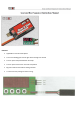
User Manual
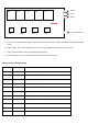


Note Table 1:
Working
Mode
F1
Radio control channel switch ON
Door 1,2 Open first
Waiting (Delay 1) time
Landing Gear Down
Radio control channel switch OFF
Landing Gear Up first
Waiting (Delay 2) time
Door 1,2 Close
Working
Mode
F2
Radio control channel switch ON
Door 1,2 Open first
Waiting (Delay 1) time
Landing Gear Down
Waiting (Delay 2) time
Door 1,2 Close
Radio control channel switch OFF
Door 1,2 Open first
Waiting (Delay 3) time
Landing Gear Up
Waiting (Delay 4) time
Door 1,2 Close
Working
Mode
F3
Radio control channel switch ON
Door 1,2 Open first
Then waiting (Delay 1) time
And Landing Gear Down
Then waiting (Delay 2) time
And Door 2 Close
Radio control channel switch OFF
Door 2 Open first
Waiting (Delay 3) time
Landing Gear Up
Waiting (Delay 4) time
Door 1,2 Close
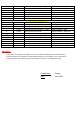
Note Table 2:
Under F1 Working Mode
FUNCTION
VOLUME
DESCRIPTION
FACTORY DEFAULTS
0
+/- 150
Door 1 opened position, +/-150%
Factory Default = 100%
1
+/- 150
Door 2 opened position, +/-150%
Factory Default = 100%
2
1 ~ 999
Delay 1, XXX* 0.1 Second
Factory Default = 10*0.1 sec
3
+/- 150
Landing Gear Down Position, +/-150%
Factory Default = 100%
4
+/- 150
Landing Gear UP Position, +/-150%
Factory Default = 100%
5
1 ~ 999
Delay 2, XXX* 0.1 Second
Factory Default = 10*0.1 sec
6
+/- 150
Door 1 closed position, +/-150%
Factory Default = 100%
7
+/- 150
Door 2 closed position, +/-150%
Factory Default = 100%
Under F2 Working Mode
0
+/- 150
Door 1 opened position, +/-150%
Factory Default = 100%
1
+/- 150
Door 2 opened position, +/-150%
Factory Default = 100%
2
1 ~ 999
Delay 1, XXX* 0.1 Second
Factory Default = 10*0.1 sec
3
+/- 150
Landing Gear Down Position, +/-150%
Factory Default = 100%
4
1 ~ 999
Delay 2, XXX* 0.1 Second
Factory Default = 10*0.1 sec
5
+/- 150
Door 1 closed position, +/-150%
Factory Default = 100%
6
+/- 150
Door 2 closed position, +/-150%
Factory Default = 100%