
User Manual
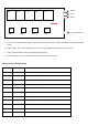


L1 to L5 is five numerical code tubes. L1 show function code, L2 to L5 show value. The details are listed in the tables
below.
FUNC+, FUNC-, VOL+, VOL- are Buttons, these are used to change the mode, to start and to set, etc.
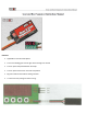
Door1, Gear and Door2 are the connectors to operate servos.
The JR connector is used to connect to your control channel on the receiver.
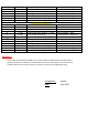
Short Description and Delay Settings
L2 to L5
Description
F
1~3
3 different running modes (Mode 1,2 and 3, see Note below)
0
700~2500
Door1 opened position,XXXμS
1
700~2500
Door1 closed position,XXXμS
2
700~2500
Landing Gear up position,XXXμS
3
700~2500
Landing Gear down position,XXXμS
4
700~2500
Door2 opened position,XXXμS
5
700~2500
Door2 closed position,XXXμS
6
1~999
Delay 1,XXX * 0.1Second
7
1~999
Delay 2,XXX * 0.1Second
8
1~999
Delay 3,XXX * 0.1Second
9
1~999
Delay 4,XXX * 0.1Second
L 1
L 2
L 3
L 4
A
B
C
D
L 5
Door 2
Door 1
Gear
To CH on Receiver
TOP VIEW
FUNC +
FUNC -
VOL +
VOL -