
User Manual

Gear and Door Sequencer Instructions Manual
Gear and Door Sequencer Instructions Manual
Features
Applicable to all scale model planes
Can control landing gear and two gear doors through one
channel
Can set up the delay time between each step
Can set up the three servos’ start and end position
Big size numerical code tube as setting interface
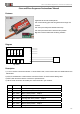
Diagram
Door2
Gear
Door1
A
B C D
L
1
L
3
L
4
L
5
L
2
Top View
Description
1) L1 to L5 are five numerical code tube. L1 show faction code, L2 to L5 show value. the details listed in the
below table.
2) A,B,C,D are Switches. A and B used to choice the Faction. C and D used to setting value
3) Door1,Gear and Door2 are the connector to operate servos.
4) JR connector is used to connected your control channel in your receiver.
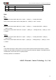
L1 L2 to L5 Description
F
1~3
3 different running mode (Mode 1,2 and 3, see Note below)
0
700~2500 Door1 opened position,XXXμS
1
700~2500 Door1 closed position,XXXμS
2
700~2500 Landing Gear up position,XXXμS
3
700~2500 Landing Gear down position,XXXμS
4
700~2500 Door2 opened position,XXXμS
5
700~2500 Door2 closed position,XXXμS
6
1~999 Delay 1,XXX * 0.1Second
1/2