
User Manual


MPU-6000/MPU-6050 Register Map and
Descriptions
Document Number: RM-MPU-6000A-00
Revision: 4.2
Release Date: 08/19/2013
32 of 46
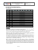
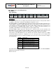
4.20 Registers 73 to 96 – External Sensor Data
EXT_SENS_DATA_00 through EXT_SENS_DATA_23
Type: Read Only
Register
(Hex)
Register
(Decimal)
Bit7
Bit6
Bit5
Bit4
Bit3
Bit2
Bit1
Bit0
49
73
EXT_SENS_DATA_00[7:0]
4A
74
EXT_SENS_DATA_01[7:0]
4B
75
EXT_SENS_DATA_02[7:0]
4C
76
EXT_SENS_DATA_03[7:0]
4D
77
EXT_SENS_DATA_04[7:0]
4E
78
EXT_SENS_DATA_05[7:0]
4F
79
EXT_SENS_DATA_06[7:0]
50
80
EXT_SENS_DATA_07[7:0]
51
81
EXT_SENS_DATA_08[7:0]
52
82
EXT_SENS_DATA_09[7:0]
53
83
EXT_SENS_DATA_10[7:0]
54
84
EXT_SENS_DATA_11[7:0]
55
85
EXT_SENS_DATA_12[7:0]
56
86
EXT_SENS_DATA_13[7:0]
57
87
EXT_SENS_DATA_14[7:0]
58
88
EXT_SENS_DATA_15[7:0]
59
89
EXT_SENS_DATA_16[7:0]
5A
90
EXT_SENS_DATA_17[7:0]
5B
91
EXT_SENS_DATA_18[7:0]
5C
92
EXT_SENS_DATA_19[7:0]
5D
93
EXT_SENS_DATA_20[7:0]
5E
94
EXT_SENS_DATA_21[7:0]
5F
95
EXT_SENS_DATA_22[7:0]
60
96
EXT_SENS_DATA_23[7:0]
Description:
These registers store data read from external sensors by the Slave 0, 1, 2, and 3 on the auxiliary I
2
C
interface. Data read by Slave 4 is stored in I2C_SLV4_DI (Register 53).
External sensor data is written to these registers at the Sample Rate as defined in Register 25. This
access rate can be reduced by using the Slave Delay Enable registers (Register 103).
External sensor data registers, along with the gyroscope measurement registers, accelerometer
measurement registers, and temperature measurement registers, are composed of two sets of
registers: an internal register set and a user-facing read register set.
The data within the external sensors’ internal register set is always updated at the Sample Rate (or
the reduced access rate) whenever the serial interface is idle. This guarantees that a burst read of
sensor registers will read measurements from the same sampling instant. Note that if burst reads are
not used, the user is responsible for ensuring a set of single byte reads correspond to a single
sampling instant by checking the Data Ready interrupt.
Data is placed in these external sensor data registers according to I2C_SLV0_CTRL,
I2C_SLV1_CTRL, I2C_SLV2_CTRL, and I2C_SLV3_CTRL (Registers 39, 42, 45, and 48). When
more than zero bytes are read (I2C_SLVx_LEN > 0) from an enabled slave (I2C_SLVx_EN = 1), the
slave is read at the Sample Rate (as defined in Register 25) or delayed rate (if specified in Register
52 and 103). During each Sample cycle, slave reads are performed in order of Slave number. If all
slaves are enabled with more than zero bytes to be read, the order will be Slave 0, followed by Slave
1, Slave 2, and Slave 3.