
User Manual

MPU-6000/MPU-6050 Register Map and
Descriptions
Document Number: RM-MPU-6000A-00
Revision: 4.2
Release Date: 08/19/2013
26 of 46
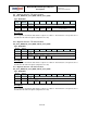
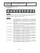
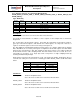
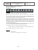
4.14 Register 55 – INT Pin / Bypass Enable Configuration
INT_PIN_CFG
Type: Read/Write
Register
(Hex)
Register
(Decimal)
Bit7
Bit6
Bit5
Bit4
Bit3
Bit2
Bit1
Bit0
37
55
INT_LEVEL
INT_OPEN
LATCH
_INT_EN
INT_RD
_CLEAR
FSYNC_
INT_LEVEL
FSYNC_
INT_EN
I2C
_BYPASS
_EN
-
Description:
This register configures the behavior of the interrupt signals at the INT pins. This register is also
used to enable the FSYNC Pin to be used as an interrupt to the host application processor, as well
as to enable Bypass Mode on the I
2
C Master. This bit also enables the clock output.
FSYNC_INT_EN enables the FSYNC pin to be used as an interrupt to the host application
processor. A transition to the active level specified in FSYNC_INT_LEVEL will trigger an interrupt.
The status of this interrupt is read from the PASS_THROUGH bit in the I
2
C Master Status Register
(Register 54).
When I2C_BYPASS_EN is equal to 1 and I2C_MST_EN (Register 106 bit[5]) is equal to 0, the host
application processor will be able to directly access the auxiliary I
2
C bus of the MPU-60X0. When
this bit is equal to 0, the host application processor will not be able to directly access the auxiliary I
2
C
bus of the MPU-60X0 regardless of the state of I2C_MST_EN.
For further information regarding Bypass Mode, please refer to Section 7.11 and 7.13 of the MPU-
6000/MPU-6050 Product Specification document.
Parameters:
INT_LEVEL When this bit is equal to 0, the logic level for the INT pin is active high.
When this bit is equal to 1, the logic level for the INT pin is active low.
INT_OPEN When this bit is equal to 0, the INT pin is configured as push-pull.
When this bit is equal to 1, the INT pin is configured as open drain.
LATCH_INT_EN When this bit is equal to 0, the INT pin emits a 50us long pulse.
When this bit is equal to 1, the INT pin is held high until the interrupt is
cleared.
INT_RD_CLEAR When this bit is equal to 0, interrupt status bits are cleared only by reading
INT_STATUS (Register 58)
When this bit is equal to 1, interrupt status bits are cleared on any read
operation.
FSYNC_INT_LEVEL When this bit is equal to 0, the logic level for the FSYNC pin (when used as
an interrupt to the host processor) is active high.
When this bit is equal to 1, the logic level for the FSYNC pin (when used as
an interrupt to the host processor) is active low.
FSYNC_INT_EN When equal to 0, this bit disables the FSYNC pin from causing an interrupt to
the host processor.
When equal to 1, this bit enables the FSYNC pin to be used as an interrupt to
the host processor.