
User Manual

MPU-6000/MPU-6050 Register Map and
Descriptions
Document Number: RM-MPU-6000A-00
Revision: 4.2
Release Date: 08/19/2013
18 of 46
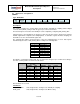
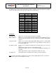
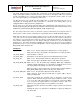
I2C_MST_CLK is a 4 bit unsigned value which configures a divider on the MPU-60X0 internal 8MHz
clock. It sets the I
2
C master clock speed according to the following table:
I2C_MST_CLK
I
2
C Master Clock
Speed
8MHz Clock
Divider
0
348 kHz
23
1
333 kHz
24
2
320 kHz
25
3
308 kHz
26
4
296 kHz
27
5
286 kHz
28
6
276 kHz
29
7
267 kHz
30
8
258 kHz
31
9
500 kHz
16
10
471 kHz
17
11
444 kHz
18
12
421 kHz
19
13
400 kHz
20
14
381 kHz
21
15
364 kHz
22
Parameters:
MUL_MST_EN When set to 1, this bit enables multi-master capability.
WAIT_FOR_ES When set to 1, this bit delays the Data Ready interrupt until External Sensor
data from the Slave devices have been loaded into the EXT_SENS_DATA
registers.
SLV3_FIFO_EN When set to 1, this bit enables EXT_SENS_DATA registers associated with
Slave 3 to be written into the FIFO. The corresponding bits for Slaves 0-2 can
be found in Register 35.
I2C_MST_P_NSR Controls the I
2
C Master’s transition from one slave read to the next slave
read.
When this bit equals 0, there is a restart between reads.
When this bit equals 1, there is a stop and start marking the beginning of the
next read.
When a write follows a read, a stop and start is always enforced.
I2C_MST_CLK 4 bit unsigned value. Configures the I
2
C master clock speed divider.
Note: For further information regarding the association of EXT_SENS_DATA registers to particular
slave devices, please refer to Registers 73 to 96.