
User Manual

MPU-6000/MPU-6050 Register Map and
Descriptions
Document Number: RM-MPU-6000A-00
Revision: 4.2
Release Date: 08/19/2013
17 of 46
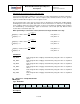
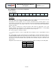
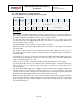
SLV2_ FIFO_EN When set to 1, this bit enables EXT_SENS_DATA registers (Registers 73 to
96) associated with Slave 2 to be written into the FIFO buffer.
SLV1_ FIFO_EN When set to 1, this bit enables EXT_SENS_DATA registers (Registers 73 to
96) associated with Slave 1 to be written into the FIFO buffer.
SLV0_ FIFO_EN When set to 1, this bit enables EXT_SENS_DATA registers (Registers 73 to
96) associated with Slave 0 to be written into the FIFO buffer.
Note: For further information regarding the association of EXT_SENS_DATA registers to particular
slave devices, please refer to Registers 73 to 96.
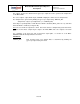
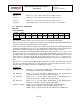
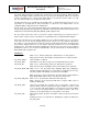
4.7 Register 36 – I
2
C Master Control
I2C_MST_CTRL
Type: Read/Write
Register
(Hex)
Register
(Decimal)
Bit7
Bit6
Bit5
Bit4
Bit3
Bit2
Bit1
Bit0
24
36
MULT
_MST_EN
WAIT
_FOR_ES
SLV_3
_FIFO_EN
I2C_MST
_P_NSR
I2C_MST_CLK[3:0]
Description:
This register configures the auxiliary I
2
C bus for single-master or multi-master control. In addition, the
register is used to delay the Data Ready interrupt, and also enables the writing of Slave 3 data into
the FIFO buffer. The register also configures the auxiliary I
2
C Master’s transition from one slave read
to the next, as well as the MPU-60X0’s 8MHz internal clock.
Multi-master capability allows multiple I
2
C masters to operate on the same bus. In circuits where
multi-master capability is required, set MULT_MST_EN to 1. This will increase current drawn by
approximately 30µA.
In circuits where multi-master capability is required, the state of the I
2
C bus must always be
monitored by each separate I
2
C Master. Before an I
2
C Master can assume arbitration of the bus, it
must first confirm that no other I
2
C Master has arbitration of the bus. When MULT_MST_EN is set to
1, the MPU-60X0’s bus arbitration detection logic is turned on, enabling it to detect when the bus is
available.
When the WAIT_FOR_ES bit is set to 1, the Data Ready interrupt will be delayed until External
Sensor data from the Slave Devices are loaded into the EXT_SENS_DATA registers. This is used to
ensure that both the internal sensor data (i.e. from gyro and accel) and external sensor data have
been loaded to their respective data registers (i.e. the data is synced) when the Data Ready interrupt
is triggered.
When the Slave 3 FIFO enable bit (SLV_3_FIFO_EN) is set to 1, Slave 3 sensor measurement data
will be loaded into the FIFO buffer each time. EXT_SENS_DATA register association with I
2
C Slaves
is determined by I2C_SLV3_CTRL (Register 48).
For further information regarding EXT_SENS_DATA registers, please refer to Registers 73 to 96.
The corresponding FIFO_EN bits for Slave 0, Slave 1, and Slave 2 can be found in Register 35.
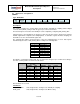
The I2C_MST_P_NSR bit configures the I
2
C Master’s transition from one slave read to the next
slave read. If the bit equals 0, there will be a restart between reads. If the bit equals 1, there will be a
stop followed by a start of the following read. When a write transaction follows a read transaction, the
stop followed by a start of the successive write will be always used.