
Installation Guide


60
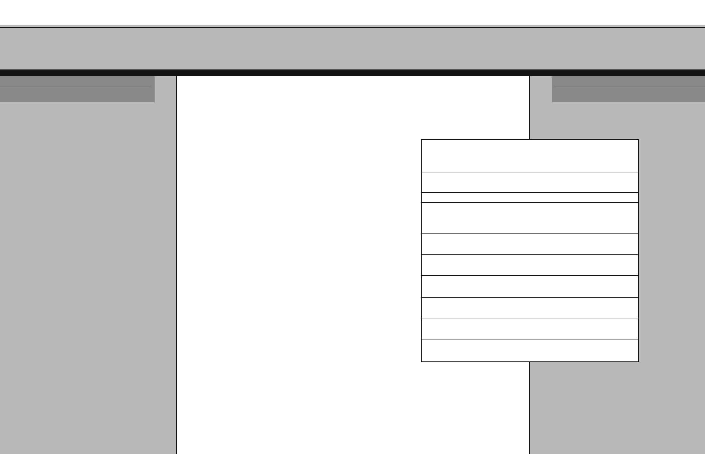
S PHERE R ULE
T ABLE
APPENDIX 5
5
9
WARNING: Prior to painting or finishing the completed
balustrade, verify all exposed ends of newels, balusters, and
railings are adequately sealed. Complete sealing is
necessary to protect the wood from weather damage.
After finishing the handrail section, the assembly can be
attached to the newel posts using two lag bolts and washers
from inside the newel post box. As an alternative, you may
choose to angle screws into the newel post from the
underside of the rail. Once the rail is secured, the newel cap
is installed and attached to the newel box using galvanized
finish nails or screws.
NOTE: For long sections in the rail assembly, support spacers
between the shoerail and the floor are recommended to
reduce sagging. The spacers should be placed every two to
three feet and at each end of the assembly.
APPENDIX 4
T HE P ROMENADE
S ERIES
MA
XIMUM
TR
EAD
PR
ODUCT
NO.BA
LUSTER
DI
AMETER
RU
N
FO
R
CO
MPLIANCE
4" SPHERE RULE 4
3
/8 " SPHERE RULE
5010 . . . . . . . . . . . . . . . . . . 1
1
/4" . . . . . . . . . . . 9
1
/4" . . . . . . . 10"
5015 . . . . . . . . . . . . . . . . . . 1
1
/4" . . . . . . . . . . . 9
1
/4" . . . . . . . 10"
5060 . . . . . . . . . . . . . . . . . . 1
1
/4" . . . . . . . . . . . 10
1
/2" . . . . . . . 11
1
/4"
5067 . . . . . . . . . . . . . . . . . . 1
1
/4" . . . . . . . . . . . 9
1
/2" . . . . . . . 10
1
/4"
5141 . . . . . . . . . . . . . . . . . . 1
1
/4" . . . . . . . . . . . 9
1
/2" . . . . . . . 10
1
/4"
1805 . . . . . . . . . . . . . . . . . . 1
3
/4" . . . . . . . . . . . 10
1
/4" . . . . . . . 11"
1815 . . . . . . . . . . . . . . . . . . 1
3
/4" . . . . . . . . . . . 9
1
/2" . . . . . . . 10
1
/4"
2005 . . . . . . . . . . . . . . . . . . 1
3
/4" . . . . . . . . . . . 10
1
/4" . . . . . . . 11"
2015 . . . . . . . . . . . . . . . . . . 1
3
/4" . . . . . . . . . . . 9
1
/2" . . . . . . . 10
1
/4"
5005 . . . . . . . . . . . . . . . . . .
1
3
/4" . . . . . . . . . . . 1
0
1
/4"
. . . . . . .
1
1
"
5105 . . . . . . . . . . . . . . . . . . 1
3
/4" . . . . . . . . . . . 10" . . . . . . . . 10
1
/4"
5300 . . . . . . . . . . . . . . . . . .
1
3
/4" . . . . . . . . . . . 9
1
/
2
"
. . . . . . . .
1
0
1
/4"
5360
. . . . . . . . . . . . . . . . . .
1
3
/4" . . . . . . . . . . .
1
1
1
/2"
. . . . . . .
1
2
1
/4"
9005
. . . . . . . . . . . . . . . . . .
1
3
/4" . . . . . . . . . . .
1
0
1
/4"
. . . . . . .
1
1
"
90
1
5
. . . . . . . . . . . . . . . . . .
1
3
/4" . . . . . . . . . . .
9
1
/2"
. . . . . . .
1
0
1
/4"
The f
ollowing chart contains columns which provide maximum tread run information
regarding the 4" sphere rule and the newer code rule of 4
3
/8" sphere rule (see boldface
explanation at the end of Step B.1a). Visit the Crown Heritage Design Library for
information on proper spacing requirements, at www.crownheritage.com.