
Installation Guide


5
3
APPENDIX 3
54
3076 Baluster Fasteners Installation Instructions
Tools Needed:
• Drill bit - 1/4”
• Reversible Drill
Optional tool:
• #3088 Dowel Driver - very helpful
NOTE: If you are using #3076 Dowel Screw with pre-drilled
balusters, skip to Step 4.
1. Cut the baluster to the needed length. The bottom of
the baluster must be cut square.
2. Mark the center of the bottom of the baluster by
drawing a line from each corner across the middle (see
Fig. A3-4).
3. Drill a 1/4” hole into the bottom of the baluster 1”
deep. Also drill a 1/4” hole into the floor or tread.
4. Drive dowel screws into the bottom of the balusters
using a drill (with the optional #3088 Dowel Driver) into
the hole in the tread or the floor and twist the baluster.
Optional Method:
Drive dowel screws into the tread or floor and then twist
t
he baluster onto the dowel screw.
Bottom of Baluster
H ARDWARE I NSTALLATION
I NSTRUCTIONS
APPENDIX 3
FIG. A3-4 - Mark the center of the bottom of the baluster
3001 Rail Bolt Installation Instructions
Tools Needed:
• Reversible Drill
• Box end wrench -
1
/2"
• Drill bits -
1
/4",
3
/8" & 1"
• Hammer
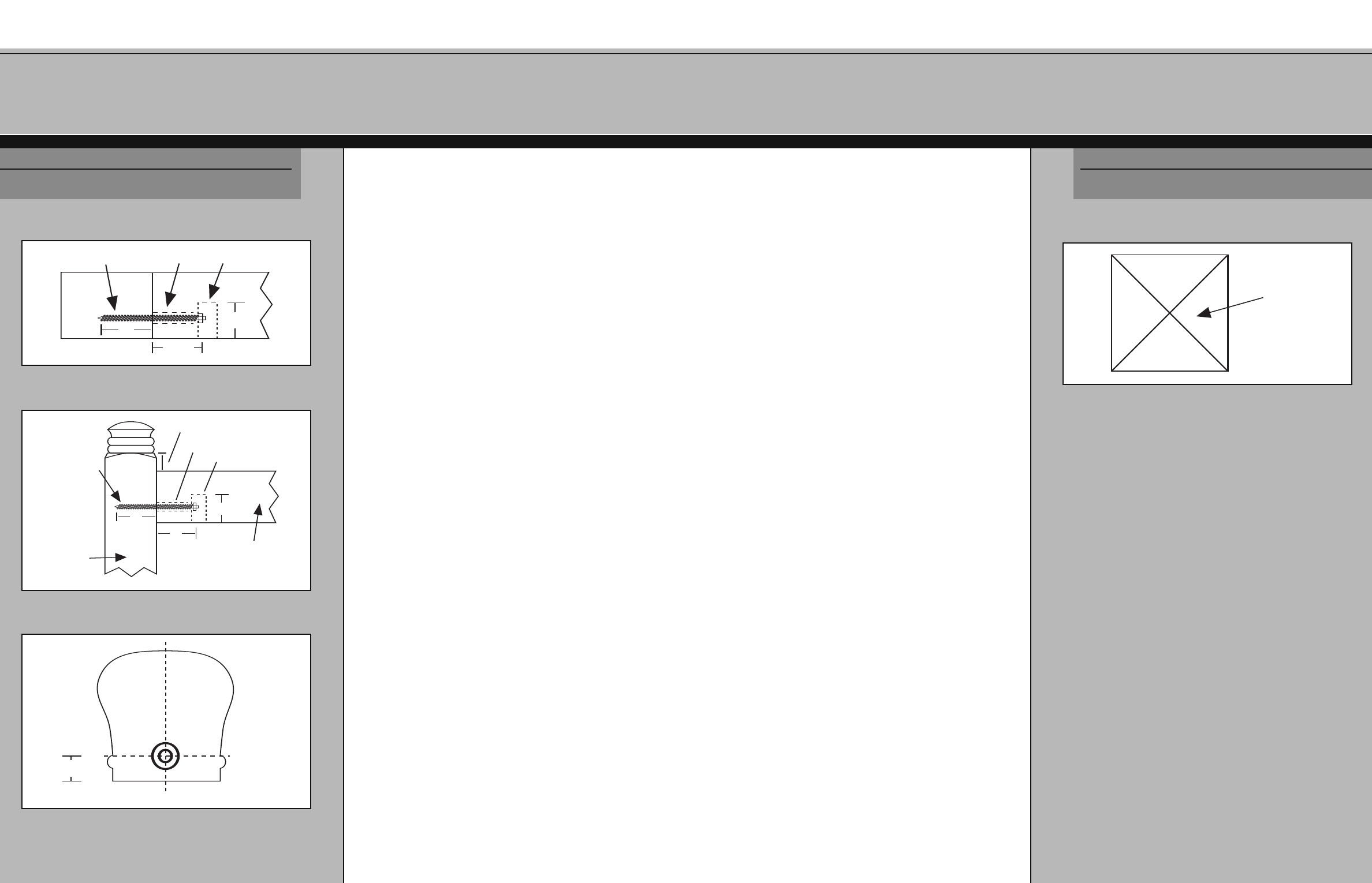
1. Saw a small
1
/4" thick piece off the end of the rail that
will serve as a template. Drill a small hole in the
template to center the bolt holes (see Fig. A3-3).
2. Cut the rail to the desired length.
3. If you are installing rail to a newel then trace the outline
of the rail template onto the newel face to help locate
the correct position of the newel for the rail.
4. If you are connecting rail to a fitting then the wood
screw should be installed into the fitting.
5. Drill a 1" hole 1
1
/2" deep in to the rail taking care not to
penetrate the top of the rail with the bit (see Fig. A3-1).
6. Drill a
3
/8" hole into the rail (see Fig. A3-1). Use the
template and see Fig. A3-3 to help position.
7. Install the screw (this will be the wood screw end of the
bolt) int
o t
he fitting or new
el face.
8.
If t
his installation is into a newel face then it will work
only at one end of the rail and newel intersection and
no
t bo
t
h ends (see F
ig. A3-3).
9.
Appl
y a small amount of wood glue to the face of
the rail.
1
0.
P
osition t
he r
ail wit
h a machine screw in the
3
/8" hole,
aff
ix the washer and nut and tighten using a box end
wrench (see Fig. A3-2). Apply wood glue to the plug
(c
hoose an oak or poplar plug) and ins
t
all int
o t
he 1"
hole in t
he bottom of the rail. After the glue is dry,
sand, flush and stain.
1/4" Hole
3/8" Hole
1" Hole
1-1/2"
2"
1-1/2"
FIG. A3-1 - Drilling holes in the rail
1" Reveal
3/8" Hole
1" Hole
1/4" Hole
Newel
Rail
2"
1-1/2"
2"
FIG. A3-2 - Attach the rail to the post
7/8"
Layout for 1/4"
and 3/8" Holes
Center Line
FIG.
A3-3 - Locate the center of the rail template
H ARDWARE I NSTALLATION
I NSTRUCTIONS