
Installation Guide


38
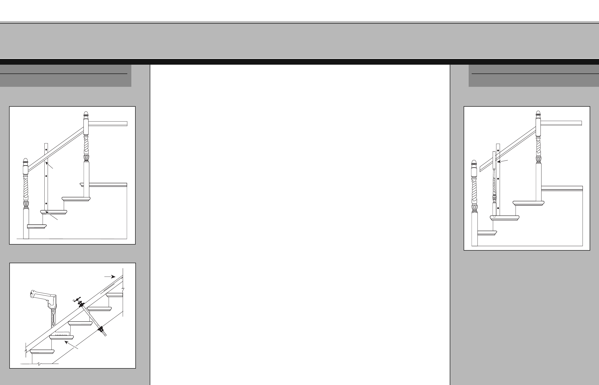
B.10b – Installing Square Top Balusters
Square top balusters are designed to fit into the groove or
“plow” in “plowed” handrail. Using a carpenter’s level,
find the location of the balusters on the handrail (see Fig.
17-5). Mark the intersection of the upstairs face of the top
square of the baluster on the handrail.
Carefully measure baluster lengths. Do not include the
mounting dowels (the plow is
1
/4" deep). Remember the
second (and third) balusters on a tread are longer than
the first.
Check baluster length on another tread at the end of the
flight. The lengths should be the same. If they are not, the
rail is not parallel to the rake of the stairway. Go back to
Step B.8 and adjust the rail.
Use the pitch block to mark the angle of cut on the top
square. Follow the philosophy outlined at the beginning of
Step B.8, rough cutting and checking angles before making
the final cut.
Complete the measuring and cutting of balusters for the
entire stairway. Carefully compare and inventory all parts
t
o assure yourself the system is complete.
The fillet, pre-packaged with the rail, will be trimmed and
ins
talled in the next step.
M
ark the handrail
along the baluster
upstairs face
S TEP
B.10b
SECTION B
FIG. 17-5 - Marking square top baluster locations
3
7
B.10a – Installing Pin Top Balusters
Pin top balusters are designed to fit into a hole drilled in the
underside of an unplowed rail. The object is to find the
centerpoints for these holes on the underside of the rail and
to be certain the balusters will be plumb.
Use a carpenter’s level to transfer the baluster centerpoint
on the tread to the underside of the handrail that was dry-fit
in Step B.9 (see Fig. 17-3). Mark each baluster centerpoint.
Carefully measure baluster lengths. Do not include mounting
dowels at the base of the baluster in your measurement. Add
1" for the depth the top of the baluster will penetrate into
the handrail. Remember the second (and third) balusters on
a tread are longer than the first.
Check baluster length on another tread at the end of the
flight. The lengths should be the same. If they are not, the
rail is not parallel to the rake of the stairway. Go back to
Step B.8 and adjust the rail.
Complete the measuring and cutting of balusters for the
entire stairway. Carefully compare and inventory all parts to
assure yourself the system is complete.
De-mount the rail and clamp the straight section across the
tread nosings (see Fig. 17-4). You may remove any fittings to
do t
his. They will be permanently reattached to the rail in
the next step.
Rotate the rail and flip over, putting the
starting newel end at the top of the flight. Using the pitch
block or a framing square to help keep the drill bit
perpendicular to the treads, drill
3
/4" diameter holes
5
/8" deep
in the center of the handrail.
With level
plumb, mark
the handrail
Baluster
centerpoint
SECTION B
S TEP
B.10a
FIG. 17-3 - Marking pin top baluster centerpoints on handrail
Use a framing square
or pitch block to align
the drill
Starting newel
end of rail
FIG. 17-4 - Drilling handrail for pin top balusters