
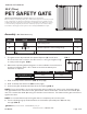
Installation Guide

Page 2 of 403/06/20
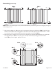
Assembly (Continued)
(C)
(C)
(C)
(C)
(B)
(B)
(B) (B)(A)
(C)
(C)
(C)
(C)
(B)
(B)
(B) (B)(C)(A)
NOTE: Make sure both stoppers are pointed downward to prevent the gate from swinging during the
assembling process.
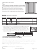
7. Adjust Space Adjusters (B) on the top by turning the locking ring clockwise (FIG. 5) until the lock
head on the handle of the swing gate fits the lock hole of the opposite part of the frame – make
sure to leave 1/32" (1 mm) between the lock head and the lock hole (FIG. 6).
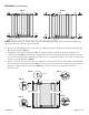
8. Now your gate is ready for use. You may turn stopper up or down depending on your preferred
swinging direction. (FIG. 7). To open gate, slide top latch while pushing up on the bottom
latch. (FIG. 8) To close gate, gently push shut.
FIG. 2 FIG. 3
2.36" (60 mm) Max2.36" (60 mm) Max
FIG. 5
FIG. 6
1/32" (1 mm)
FIG. 8
FIG. 7
FIG. 4
(B)
(B)