
Product Literature

SPECIFICATIONS
Operational
• Flow Range:
– 1” – 5 to 40 gpm – 1¼” – 20 to 100 gpm
– 1½” – 20 to 130 gpm – 2” – 30 to 180 gpm
• Operating Pressure (220 psi maximum pressure rating):
– Electric – 10 to 220 psi
• Pressure regulating:
– Outlet: 5 to 100 psi ± 3 psi
• Inlet: 10 to 220 psi
• Minimum pressure differential (between inlet and outlet) for pressure
regulation: 10 psi (2" is 20 psi)
• Burst pressure safety rating: 750 psi
• Body style:
– Globe valve – 1”, 1¼”, 1½”, 2” female threads
• Spike Guard
™
Solenoid: 24 VAC (50/60 Hz) Standard
– Inrush: 60 Hz: 0.12 amps
– Holding: 60 Hz: 0.1 amps
• DC latching – momentary low voltage pulse
Dimensions
• 1” – 5¼” H x 5” W
• 1¼” – 6½” H x 6” W
• 1½” - 6½” H x 6” W
• 2” – 7½” H x 7” W
Warranty
• Five years
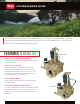
Fabric Reinforced
Diaphragm
Provides superior
performance and
extended life without
tearing in high pressure
applications.
Specifying Information—220G Brass Series
220G-27-0XXX
Type Body Style Size Optional
220G 27 OX XX
220G—220G Brass Series Valve 27—NPT, Pressure-regulated (5–100 psi) 4—1" 6—1
1
⁄2”
5—1
1
⁄4" 8—2”
DL—Latching Solenoid for 2-wire GDC Systems
E—Effluent
Example: A 1" NPT pressure-regulated, 220G Brass Series Valve with 60 Hz solenoid, would be specified as: 220G-27-04
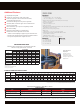
VALVE WIRE SIZING CHART
Maximum One-way Distance (in ft.) Between Controller
and Valve Using Spike-Guard
™
Solenoid*
Ground Wire
Control Wire
18 16 14 12 10 8 6
18 2040 2520 2940 3280 3540 3720 3860
16 2520 3260 4000 4660 5220 5620 5920
14 2940 4000 5180 6360 7420 8300 8960
12 3280 4660 6360 8240 10100 11800 13180
10 3540 5220 7420 10100 13180 16060 18770
8 3720 5260 8300 11800 16060 20800 25540
6 3860 5960 8960 13180 18700 25540 33080
* Solenoid Model: 24 V ac
Pressure: 150 psi
Voltage Drop: 4 V
Minimum Operating Voltage: 20 V
Amperage (peak) 0.12 A
Additional Features
Diaphragm stem guide
Ingot brass and stainless steel construction
Pressure regulates in electric and manual modes,
serviceable under pressure
Forward-flow design for more precise regulation
Standard, built-in Schrader-type valve for downstream
pressure verification
Anti-vandal dust cap on pressure-regulating models
No external tubing
External manual bleed for system flushing
Manual flow control: adjustable to zero flow
– Stainless steel diaphragm support ring for minimum wear
– Stainless steel solenoid seat for longer life and positive shuto
– Low-power requirement for longer wire runs
220 BRASS SERIES FRICTION LOSS DATA
Model Type
gpm Flow
5 10 15 20 30 40 50 60 70 80 100 120 150 170 180 200 250 300 350
1" Electric 1.75 2.0 2.2 3.10 5.05 7.80
1
1
/4”
Electric 1.85 2.50 2.70 3.50 4.10 5.6
1
1
/2”
Electric 2.15 2.45 2.80 3.05 3.80 5.0 6.55
2" Electric 3.05 3.20 2.90 2.95 3.25 3.40 4.50 6.55 10.10 13.45 14.85
Notes: For optimum performance when designing a system, calculate total friction loss to ensure sufficient downstream pressure.
For optimum regulation performance, size regulating valves toward the higher flow ranges.
■
Flow rates are recommended not to exceed 5 psi loss.
www.toro.com / The Toro Company, Irrigaon Division / 5825 Jasmine Street, Riverside, CA 92504 / 877-345-8676 / Specicaons subject to change without noce / © 2016. All rights reserved / P/N 16-5016-IG