
Installation Guide


30
Installation Practices
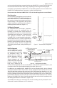
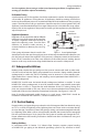
4.8 Pressure Regulators
Installation Requirements
A HOME-FLEX® gas piping system used with inlet gas pressures in excess of ½ PSI, but servic-
ing appliances rated for a maximum of ½ PSI, must contain a pounds-to-inches regulator to
limit the downstream pressure to no more than ½ PSI. Gas pressure regulators must comply
with a nationally recognized standard for pressure regulators such as ANSI Z21.80/CSA 6.22.
Regulators must also conform to the following:
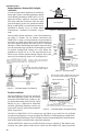
• Regulators must be sized in accordance with the total appliance load (maximum
ow rate), largest single appliance ow rate, inlet pressure range at the regulator
inlet, and the desired outlet pressure. (Table 4.5 and Table 4.6)
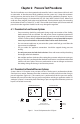
• Regulators must be installed in accordance with the manufacturer’s instructions.
Ensure the ow of gas is correct, as indicated by the ow markings on the regula-
tor casing.
• The regulator must be installed in a fully accessible area with an approved shut-o
valve upstream. A union can be used to allow for removal of the regulator if the
location doesn’t allow proper room for regulator servicing.
• Where a gas line pressure regulator is used in a system with a source pressure in
excess of 2 PSI to serve appliances rated for 1/2 PSI or less, a regulator with an
integrated over-pressure protection device (OPD) must be used. The regulator
with OPD must be
assembled and listed
by the regulator manu-
facturer in accordance
with ANSI Z21.80, Stan-
dard for Line Pressure
Regulators.
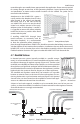
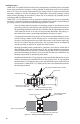
Vent Limiters and Vent Lines
Regulators must be equipped with a manufacturer-supplied vent limiting device, or be capa-
ble of being vented outdoors. When installed indoors, the vent-limiting device is to be used.
When a vent-limiter is used, the regulator must be mounted in an upright position for proper
function. For outdoor venting, the vent line must be at least the same size as the regulator
vent connection and not exceed a length of 30 feet. The vent must be designed to prevent
entry of water or other foreign materials that could clog the line. DO NOT vent to an appliance
ue, building exhaust system, or pilot light.
If installing the regulator outdoors, remove the vent limiter and mount the regulator with the
vent outlet pointing toward the ground to prevent water from entering. If the manufacturer
provides a cap for outdoor installations, this can be used and the regulator can be mounted
right side up.
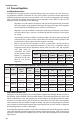
Table 4.5 Pressure Drop for Natural Gas in CFH (m
3
/hr)
Model
7" w.c.
(17 mbar)
½ PSI
(34 mbar)
¾ PSI
(52 mbar)
1 PSI
(69 mbar)
325-3 145 (4.0) 204 (5.8) 250 (7.0) 289 (8.2)
325-5A 339 (9.6) 476 (13.5) 583 (16.5) 673 (19.1)
Table 4.6 Regulator Capacity Tables in CFH (m
3
/hr) (MBTU/hr values based on LP Gas with heating value of 2520 BTU per ft
3
)
Part No. Gas Type
Max. Single
Appliance
Load
Max. Total
Load
Outlet
Pressure
Set Point
Operating Inlet Pressure
½ PSI ¾ PSI 1 PSI 1½ PSI
325-3
Natural
(0.64 sp. gr.)
140 CFH 250 CFH
8" w.c. 145 (4.1) 200 (5.7) 250 (7.1) 250 (7.1)
11" w.c. 93 (2.6) 172 (4.9) 225 (6.4) 250 (7.1)
LP
(1.53 sp. gr.)
91 CFH
(229 MBTU/hr)
163 CFH
(410 MBTU/hr)
11" w.c.
60 (1.7)
(152 MBTU/hr)
112 (3.2)
(281 MBTU/hr)
146 (4.1)
(368 MBTU/hr)
162 (4.6)
(409 MBTU/hr)
325-5A
Natural
(0.64 sp. gr.)
300 CFH 550 CFH
8" w.c. 335 (9.5) 475 (13.5) 550 (15.6) 550 (15.6)
11" w.c. 211 (6.0) 391 (11.1) 511 (14.5) 550 (15.6)
LP
(1.53 sp. gr.)
195 CFH
(483 MBTU/hr)
358 CFH
(901 MBTU/hr)
11" w.c.
286 (8.1)
(345 MBTU/hr)
254 (7.2)
(639 MBTU/hr)
332 (9.4)
(836 MBTU/hr)
357 (10.1)
(899 MBTU/hr)