
Installation Guide

29
Manifold Stations
routed through a non-metallic sleeve appropriate for the application. Sleeves are not required
for routing through ceramic liner in heat generating replaces. Spaces between the jacket
and penetration at interior and/or exterior locations can be caulked. The jacket can be
removed inside the rebox.
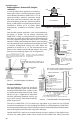
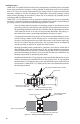
Attachment to the HOME-FLEX® system is
usually made at the replace shut-o valve,
often located in the control area beneath
the burner unit or at the side of the log
set. HOME-FLEX® can be run into the lower
control area without removal of the poly-
ethylene jacket. If the replace is vented, it
is suggested to remove the yellow jacketing
inside the re box to prevent direct ame
contact with the jacket.
If installing HOME-FLEX® through sheet
metal enclosures (as commonly used for
decorative replaces), it is recommended
to leave the protective yellow jacketing in
place through the penetration. HOME-FLEX® should be secured to the building structure out-
side the replace to limit motion after installation. Installations that may lead to abrasion of
HOME-FLEX®, such as vibration from a fan in the replace assembly, require a short piece of
Flexible Protective Conduit or PVC pipe to insulate the HOME-FLEX® from the enclosure.
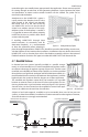
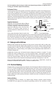
4.7 Manifold Stations
In elevated pressure systems (typically installed in a parallel arrange-
ment), it is recommended to use a central manifold and regulator station
to take best advantage of regulator capacity (Figure 4.25). Stainless steel
manifolds are available from Valencia Pipe Company or can be assembled
through the use of rigid black steel pipe and fabricated tee manifolds. It is
recommended that the station be located near the appliance(s) with the
highest load in the system to allow for shorter runs to those appliances.
The manifold and regulator station MUST be located in an accessible
location to maintain access to the shut-o valves and regulator. The sta-
tion may be housed in a gas load center enclosure (Figure 4.24). Optional
shut-o valves can be mounted on the manifold to control each appli-
ance run in addition to the main line shut-o valve.
Subject to local code approval, manifolds may be concealed when used in low pressure
systems, or when the manifold is installed in a location removed from the regulator. However,
accessible locations are strongly recommended.
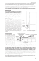
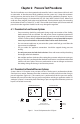
Figure 4.23 Routing to Masonry Fireplace
CSST through
stud walls
Sleeve (if
required)
CSST through
basement or
crawl space
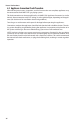
Figure 4.24 Gas Load Center
Figure 4.25 Example of Manifold Station Layout
Elevated pressure from gas meter
Line shut-off approved
valve
Dirt trap pocked (per
code)
Vent Limiter
House line
regulator
Union
Manifold
Low pressure to appliances
HOME-FLEX®
Fittings