
Installation Guide

21
Routing
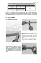
assembly, wrap with the assembly with self-bonding silicone tape from the tubing jacket to
the end of the nut ange.
4.3 Routing
General Routing Practices
Routing requirements for CSST exible gas pipe can vary by locality. Be sure to conrm the
requirements of the administrative authority for the location where HOME-FLEX® is to be
installed before installing HOME-FLEX®. In general, HOME-FLEX® can be routed:
• Beneath, through, and along side oor and ceiling joists. This is typical for residen-
tial and commercial installations with basements or multi-oor routing.
• Inside hollow interior wall cavities. Routing inside wall cavities is preferred for ver-
tical sections of tubing. Horizontal runs through wall cavities should be avoided to
minimize the need for striker protection from puncture hazards.
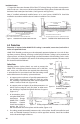
• Through approved conduit underground or under building slabs. Under no cir-
cumstances is HOME-FLEX® to be routed underground or under slab unless it is
routed within a non-metallic water-tight conduit that is at least ½" larger than the
outer diameter (OD) of the CSST tubing. Fittings and joints are not permissible in
such runs—the run must be one unbroken line of tubing. Runs underneath slabs
must be sleeved and vented per local codes.
• Outdoors. When installed outdoors, the yellow jacketing of HOME-FLEX® must be
intact along the entire run. Any areas of exposed tubing are to be wrapped with
self-bonding silicone tape or sleeved to prevent threats from acids or chlorides.
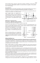
• Along the perimeter of a building. Care must be taken to protect HOME-FLEX®
from mechanical damage when installed along the exterior of a building. If
installed within 6 feet of the ground, HOME-FLEX® tubing must be routed within
a conduit or chase. If installed in a location where the tubing will not be subject
to possible mechanical damage, a conduit is not required, but is recommended.
Careful consideration should be given to route HOME-FLEX® tubing in areas where
mechanical damage is least likely.
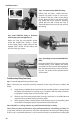
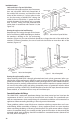
Clearance Holes and Notching
Clearance holes for routing tubing through
studs, joists, plates, etc. must have a diameter
at least ½" larger than the outside diameter
of the tubing (Table 4.3). Local codes pertain-
ing to structural members must be followed
when drilling clearance holes—no structural
members should be compromised, weakened
or impaired by cutting, notching, drilling, or
otherwise alternating the member.
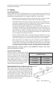
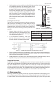
Routing through holes in joists, rafters or similar wood structures
When HOME-FLEX® tubing is installed through bored
holes in joists, rafters, or other wood structures, the
holes should be bored such that the edge of the hole
is at least 2 inches from the nearest edge of the wood
structure (Figure 4.2). If this criterion can’t be met, the
tubing must be protected by a striker plate of suitable
size installed in accordance with Section 4.4 (p. 24).
The diameter of the hole should be no more than 1/3
the depth of the wood structure.
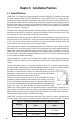
Table 4.3 Recommended Routing Holes for Installation
of HOME-FLEX® Tubing
Tubing Size Drill Hole Size
½" (13 mm) 1⁄" (35 mm)
¾" (19 mm) 1½" (38 mm)
1" (25 mm) 1¾" (45 mm)
Figure 4.2 Holes in Wood Structures
Preferred
location
D/3
Max
D/3
Max
D
2"
Min
2" Min