
Replacement Part List


G01-R01-0704
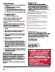
STEP 15 – Attaching an Automatic Opener
IMPORTANT: To avoid damage to your door, you must
reinforce the top section of the door in order to provide a
mounting point for the opener to be attached. Refer to the
section of this manual titled Reinforcing the Top Section on
page 14 for specic instructions. Failure to reinforce the door
as illustrated will void the warranty on your door.
To avoid risk of strangulation or personal injury to
children, if your door has a pull rope, you must remove
the pull down rope when you install an automatic garage
door opener.
IMPORTANT: When installing an automatic garage door
operator, make sure to follow manufacturer’s installation and
safety instructions carefully. Remove the pull down rope and
unlock or remove the lock. If attaching an operator bracket
to the wooden anchor pad, make sure the wood anchor pad
is free of cracks and splits and is rmly attached to the wall.
Always drill pilot holes before attaching lag screws.
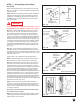
The operator arm will usually be attached to the vertical
reinforcement member at roughly the same height as the top
roller of the door. Attach the opener arm to the reinforcement
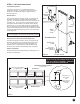
as shown in Figures 15-B to 15-D. To prevent the top of the
door from bending, the opener rail should be mounted no less
than 2" and no greater than 5" from the face of the door with
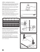
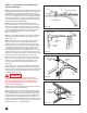
the door in the open position (FIG. 15-A). Additionally, when
the door is closed, the portion of the operator arm attached to
the door should be at angle of approximately 60 degrees from
the vertical (FIG. 15-B).
WARNING
Opener Rail Mounting Distance
Ceiling
Opener Rail
Horizontal Track
Keep Clearance at 2"–5"
Top View
(assembled)
Opener
Arm
Lock These
Nuts Together
Securely
Leave
Clearance
Mounting
Surface Of
Door
Vertical Punched
Angle
Opener Arm
3/8" x
1-1/2"
Hex Bolt
3/8"
Hex Nut
Vertical
Punched
Angle
Horizontal
Punched
Angle
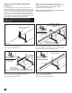
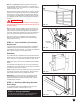
Opener Arm Attachment To Vertical Angle
FIG. 15-A
FIG. 15-D (Doors with Angle Iron Reinforcement
Bracket and Stile in Center of Door)
18
FIG. 15-B (Doors with supplied Reinforcement Bracket
and Stile in Center of Door)
60°
Clevis
Pin
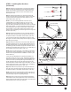
FIG. 15-C (Doors with odd number of Panels)
Punched
Angle
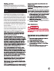
Opener Arm Attachment To Horizontal Angle Or Strut
Horizontal Angle
Or Strut
Opener Arm
Supplemental
Bracket (Not Available
On All Doors)
Lock These Nuts
Together Securely
Punched
Angle
Horizontal
Angle
Or Strut
Front View (Assembled)
Opener Arm