
Replacement Part List


G01-R01-0704
Slide
Top Roller
Bracket
Slide
Bolts
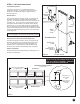
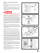
Step 11- 8, Continued: Adjust the position of the tracks if
the squareness distances are not within 1/2" of each other.
Horizontal track can be out of level up to 1" from front jamb to
rear track hanger. (FIG. 11-I)
When the track is square and level with the opening, the track
hangers can be fastened permanently to the ceiling trusses.
Three 5/16" x 1-1/2" lag screws are recommended. Be sure
3/16" pilot holes are drilled before installing 5/16" lag screws.
The attachment must be strong enough to hold the weight of
the door.
Use adequate length screws to fasten rear track hangers
into trusses. Door may fall and cause serious injury if not
properly secured.
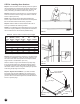
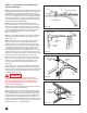
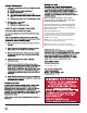
Step 11- 9: With the track installed, the top door section can
now be properly adjusted. With the slide on the top bracket
loose, force the top of the door against the stop molding or
door jamb. Pull the roller towards you so it is tight against the
groove in the track and tighten the slide bolts. (FIG. 11-J)
At this time, remove the 3" nails that were used to hold
sections in place prior to installation of the track assembly.
(Refer back to FIG. 9-B.)
STEP 12 – Lock Installation (If Included)
Keyed Lock:
If your door has an exterior keyed lock, please complete the
installation of the lock at this time following the instructions
provided with your lock hardware. If your door has a slide bolt
lock, install according to the instructions below.
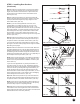
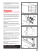
Slide Bolt:
The inside slide bolt is installed on the end stile of the second
section using (4) #14 x 5/8" hex head sheet metal screws (steel
doors) or (4) 1/4" x 1" lag screws (wood doors). (FIG. 12-A)
NOTE: 3/16" holes may have to be predrilled before installing
screws.
The slide bolt rests against the top of one of the rectangular
engaging slots in the vertical track. Proper alignment is easier
to achieve by using track as a guide.
NOTE: It may be necessary to knock out the slug in the vertical
track to open the slot for lock engagement. Remove slug by
striking with a hammer from the outside of the track.
IMPORTANT: If your door is going to be equipped with an
automatic garage door opener, make sure that the door is
always unlocked when the opener is being used. This will
avoid damage to the door.
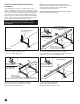
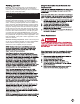
STEP 13 – Pull Rope (Manually Operated
Doors Only)
To complete the door section installation, tie the pull rope
provided to the bottom roller shaft. (FIG. 13-A)
STEP 14 – Spring Installation
It is now time to install the spring. Proceed to springing
instructions that came with your spring hardware.
WARNING
Pull Rope
FIG. 13-A
FIG. 11-J
FIG. 11-I
FIG. 12-A
#14 x 5/8" Sheet Metal Screw or 1/4" x 1" Lag Screw
17