
Manual

92 | P a g e
Aux 2
IN/OUT
+
+
-
-
Aux 1
RELAY/OUT
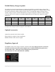
Aux 1 and Aux 2 Graphs/Jumpers
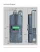
Figure 3.0 shows the two Aux port terminals, with their respective
polarities. These terminals are located at the bottom of the
power board below the battery temperature jack. Use a mini
flat head screw driver to tighten the screws. The jumpers are
described in the section below.
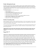
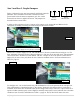
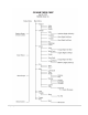
In order to select operation of Aux 1 between relay contact or 12v output JP6 and JP8 need to be
configured accordingly following the instructions provided in this section.
When Aux 1 is used to supply 12v out, JP6 and JP8 have to be in the position shown in Figure 3.1. The
basic schematic of how this works is shown in Figure 3.2. The 12v out is more like 14.5v. The maximum
current from Aux 1 should not exceed 200mA. The Aux 1 output can be set to operate at either Active
High (12V) or Active Low (0V) when the Aux 1 function condition is true. For more information see
Table 2.1, page 31.
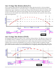
To configure Aux 1 to use the internal relay, JP6 and JP8 have to be in the position shown in Figure 3.4.
This configuration is commonly known as ―dry contact‖ because it does not provide 12v at the Aux1
terminals; it acts more like an isolated switch (to the ratings of the relay). The Aux 1 output can be set to
operate at either normally open, (Active High) or normally closed (Active Low) when the Aux 1 function
condition is true. For more information see Table 2.1, page 31. This is ideal for an Auto Gen Start.
Figure 3.1
JP6 and JP8 positioned to supply 12v out of the Aux 1 terminals
Figure 3.2
Figure 3.3
Figure 3.4
Figure 3.0