MidNite Solar Classic Owner’s Manual This Manual covers models Classic 150, 200, 250 &250KS 1|Page
The MidNite Solar Classic charge controller conforms to UL 1741, Safety for Inverters, Converters, Controllers and Interconnection System Equipment for Use With Distributed Energy Resources, Second Edition, May 7, 1999 with revisions through January 28, 2010 and CAN/CSA C22.2 No. 107.1: 2001/09/01 Ed: 3 (R2006) Note: The Classic KS has not been evaluated by ETL. Notice of Copyright MidNite Solar's Classic charge controller User‘s Manual Copyright ⓒ2010 all rights reserved. MidNite Solar Inc.
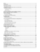
Scope..........................................................................................................................................................5 Introduction ..............................................................................................................................................5 Classic Power Curves ...............................................................................................................................8 Unpacking the Classic.......................
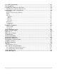
View Faults and Warning's ...................................................................................................................40 View Logged Data ..................................................................................................................................40 Uploading New Firmware to the Classic ..............................................................................................40 Updating Classic Firmware (Windows XP) ............................................
Scope This Manual provides safety guidelines and installation information for the Classic charge controller. It does not provide brand specific information about photovoltaic panels, batteries etc. Contact the manufacturer of other components in the system for relevant technical data. Introduction The MidNite Classic charge controller is unique in its ability to be used for a great variety of DC input sources. The Classic is designed to regulate DC input from PV, Hydro, Wind and other DC sources..
• The Charge Controller equipment ground is marked with this symbol: • If damaged or malfunctioning, the Charge Controller should only be disassembled and repaired by a qualified service center. Please contact your renewable energy dealer/installer for assistance. Incorrect reassembly risks malfunction, electric shock or fire. • The Charge Controller is designed for indoor installation or installation inside a weatherproof enclosure.
If battery acid contacts skin or clothing, wash immediately with soap and water. If acid enters an eye, flood the eye with running cool water at once for at least 15 minutes and get medical attention immediately following. Baking soda neutralizes lead acid battery electrolyte. Keep a supply on hand in the area of the batteries. NEVER smoke or allow a spark or flame in vicinity of a battery or generator. Be cautious to reduce the risk of dropping a metal tool onto batteries.
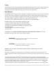
Classic Power Curves 8|Page
Figure 2.1 The graphs above represent the max power output for a given input for each Classic. Using and understanding these power graphs will help maximize Classic‘s output power and aid in selecting wire and breaker/disconnects. The built in set up wizard also helps select breakers and wire sizes. Notice that lower battery voltages and lower PV input voltages result in higher continuous output power. The PV voltages listed are for reference and are not intended to be the only PV voltages supported.
Unpacking the Classic When you receive your Classic you will want to unpack it and make sure everything is there and in good shape. Refer to Figure 1.1.
*1 ten foot custom USB cable **Note. These items are optional email customerservice@midnitesolar.com for more information If anything is missing or damaged please refer to Page 2 for details on contacting us. Figure 1.1 Removing and installing the front cover on the Classic Removing the front art deco cover is required to gain access to the wiring compartment. Be aware there is a cable connecting the cover to the electronics. Do not pull hard or fast as damage could occur.
Mounting the Classic The following section covers typical mounting arrangements. If you require additional details that are not covered here please contact our technical support team. The Classic is designed to be directly mounted onto the MidNite Solar E-Panel. The Classic can also accommodate other installation methods as well. Mount in an upright position out of direct sunlight when possible.
Classic has four one inch knock outs that are pre cast. The Classic has mounting locations and conduit locations are similar to other brands of charge controllers to facilitate ease of upgrading older technologies. Mounting the Classic directly to the E Panel: *Remove the front cover of the Classic. *Install the mounting bracket on the E Panel and start the upper mounting screw into the bracket leaving it about half way out so you can hang the Classic on this screw.
Install locknut here to act as a spacer. Alternative Mounting To mount the Classic to a plywood surface use 1 1/2‖ wood screws in the top key hole slot hole and the holes in the wiring compartment. Taking care to make sure the Classic is Plumb and Level. Dimensions See page 40 for more details. Sealed or Vented The Classic has the ability to be sealed for protection from salt air or dust. It comes from the factory Vented. If you live in a dusty or salt air environment you may wish to seal the Classic.
plastic knock out covers into any unused knock outs and snap the upper vent cover onto the Classic as seen in the photo below. Note that the Classic will be slightly de-rated (puts out less power) by sealing it. Refer to the specifications page of the owner‘s manual for the ratings in the sealed mode. To obtain the parts necessary to seal the Classic please contact our Technical Support Team. Refer to Figure 1.4 and 1.5 Figure 1.4 Figure 1.
Master Classic Slave Classic Figure 1.
Cable Clamp for network cables Battery Temp Sensor USB connector 10 foot USB cable is included Ethernet connector Figure 1.7B Battery Temperature Sensor Installation CAUTION - To reduce risk of injury, charge only deep-cycle lead acid, lead antimony, lead calcium, gel cell or absorbed glass mat type rechargeable batteries. Other types of batteries may burst, causing personal injury and damage. Never charge a frozen battery. WARNING: RISK OF INJURY.
Figure 1.8 Insert BTS to the jack labeled BATTERY TEMP on the control board. Figure 1.
Chassis Grounding In all installations the Classic chassis should be connected to ground. For systems with a battery breaker sized 60 amps and smaller 10 AWG (6 mm2) copper is generally sufficient. For systems with a battery breaker sized 100 amps and smaller 8 AWG (10 mm2) copper is required. For grounding conductor requirements on your specific installation please consult your local electrical code.
DC GFP (Ground Fault Protection) The Classic has internal ground fault protection (GFP) built in. Since 2008 the NEC requires a DC-GFP on all PV systems in the USA. The built in DC-GFP eliminates the need to purchase and install an external DC-GFP. If the internal grounding jumper is installed in a Classic, the battery negative and DC source negative must not be connected to the system grounding conductor anywhere in the system. Grounding of these circuits will defeat the GFP function.
Wiring the Classic WARNING: Shock hazard. Disconnect the batteries and input power before opening the Classic front cover When two or more Classics are paralleled onto one DC Source a blocking diode must be used between each Classic and the input source to isolate each Classic from the other ones. The Classic should be wired by a qualified professional and needs to meet all applicable electrical codes.
Figure 2.
DC Terminal Connector Figure 2.4 The Classic's DC terminal connector is located on the circuit board as shown in. The connector will take up to a #4 AWG. #4 AWG THHN when installed in the Classic and MidNite E-Panel is rated for over 100 amps and is therefore suitable for the highest power available from the Classic 150.
Temperature Current Limit The Classic has a current limit component which interacts with the temperature of the charge controller. If the Classic is exposed to extremely hot ambient conditions the output current will be reduced automatically to keep the charge controller safe, if the orange LED comes on, on the MNGP it means that the Classic is in current limit mode. If you believe the Classic is not hot and the orange LED is on, most likely the current limit set point is too low.
Connecting the Classic to the Clipper Not Yet Available Please email customerservice@midnitesolar for status updates on the Clipper. Maximum and Minimum Wire Size The Classic DC terminal connector will accept wire from #14-#4 AWG Commissioning the Classic The Classic will enter into the setup wizard upon initial power up. If the Classic does not enter into the setup wizard or you want to enter the wizard at any time follow these steps to get into the setup wizard. Press the Main Menu button.
DO YOU KNOW THE BATTERY BANK AMP HR CAPACITY YES NO WHAT IS THE VOLTAGE OF AN INDIVIDUAL BATTERY 6 SET CURRENT LIMIT 80 ENTER TO CONTINUE CONTROLLER MODE SOLAR WIND HYDRO SCROLL < > TO SELECT THEN PUSH ENTER STC MODULE POWER 210 ^ WATTS STC VOC RATING 44.3^ VOLTS STC ISC RATING Helps set Absorption time and EQ defaults This is necessary for the set up software to help figure out battery capacity Sets classic‘s max output current Selects classic‘s mode.
Float A Float cycle follows after the Absorb cycle is completed; Float is displayed on the screen. Battery voltage is held at the float voltage set point, float time can be changed by the user. Equalize Equalization function has to be enabled by the user, refer to page 25. The intent of an equalization charge is to bring all battery cells to an equal voltage by a deliberate overcharge.
Note. Use the description below to help complete the calibration of the Classic voltages. TWEAKS screen Battery voltage adjust PV in voltage adjust PV in voltage offset Battery voltage offset Displayed battery voltage Displayed battery voltage Figure 2.7 Configuring DC Input Source To select the Mode the Classic will run in, follow the steps below. Push the Main Menu button. Scroll left or right until Mode is highlighted and then push the Enter button.
shaded (if this feature is enabled). SOLAR mode is best suited for shaded or un-shaded PV arrays that are at least one nominal voltage above the battery voltage. For severe partial shading or PV arrays with nominal voltage equal to battery voltage, you may also want to try Legacy P&O (Perturb and Observe) MPPT mode.
useful for testing or constant voltage sources. The ON/OFF has to be set to OFF in order to change the operational mode. Scroll to the right to highlight the word ON or OFF and use the up and down keys to change it to OFF. Push the Enter button to save this change. Now you can scroll to the right and highlight the mode under Function. Scrolling up or down changes the modes. Once a mode is selected push the Enter button to save this change. Then you can use the right soft key to select ―setup‖.
helps determine when the Classic wakes up and when it goes to sleep. This setting tells the Classic when sunrise and sunset are to happen. The Classic will use this information on future features also. To set longitude and latitude coordinates you need to go thought the WIZARD that is the only way to gain access of this feature Configuring Auxiliary Input/Output The Classic includes two auxiliary ports which can be configured to become inputs or outputs.
Aux 1 Vent Fan Lo This mode will turn Aux 1 off above the voltage set point you program. It allows you to run a vent fan for a battery bank based on battery voltage. There is a voltage set point that you set and Aux 1 will turn off when the battery reaches that set point. The voltage has to fall 2 tenths of a volt below the set point for 30 seconds before Aux 1 will turn back on. Vent Fan High This mode will turn Aux 1 on above the voltage set point you program.
Pv V on High This Mode will turn Aux 1 on above a user set voltage based on the input voltage to the Classic ( V High) and turn Aux 1 off when it hits a low voltage set point (V Low). It also allows you to set a delay time in seconds the Classic will wait before turning Aux 1 on after reaching the V High set point. It also allows you to set a hold time in seconds the Classic will wait before turning Aux 1 off after reaching the V Low set point.
Aux 2 Float Low This mode will turn Aux 2 off whenever the Classic is in Float. Aux 2 will stay off until the Classic falls 3 tenths of a volt below the float voltage set point. Float High This mode will turn Aux 2 on whenever the Classic is in Float. Aux 2 will stay on until the Classic falls 3 tenths of a volt below the float voltage set point. Day Light This mode will turn on Aux 2 at sunrise and turn it off at sunset based on the PV input voltage.
Opportunity Hi This mode is PWM based and will PWM Aux 2 when the Classic gets within a certain range of the voltage set points for each charging stage (V High) and stop when it gets to a low set point (V Low). These set points are user adjustable and will allow the Absorb, Float and EQ timers to continue to run. You will adjust these set points to negative numbers and the numbers are an offset from the voltage set point. For example a -.2 would turn Aux 2 on 2 tenths of a volt below your set points.
Aux 2 Function.
Figure 2.8 Screen name Communication indicator Menu name USB activity indicator Menu description Current limit indicator Right soft key Speaker Up arrow key Right arrow key Left soft key Left arrow key Main Menu Status screen Enter button Down arrow key Operating the Classic Once the parameters have been set via the set up wizard or from manual set up, there are no further requirements to make the Classic function. It is all automatic.
the submenu where you will be able to change the parameters of the unit. To get out of the submenus push MAIN MENU, this will take you out of the submenus one at a time every time you push it. See page 44 for entire Menu Map. Viewing Other MidNite Products on the Display The Classic is able to view other products or Classics connected to the network. For example: the MidNite Solar Clipper.
Arc Fault The Arc Fault Detector is a unique safety component included in every Classic, because safety is not an option, the engineers at MidNite take action as the 2011 NEC code requires. The Classic is the first charge controller in the world to successfully stop a series arc. The Classic can detect an arc in less than 100mSec.
In order for the Classic to read the new settings you must power cycle the Classic. Do this by turning the DC source (PV, Wind or hydro etc.) breaker off. Then turn off the external battery breaker. Than simply turn the 2 breakers back on starting with the battery breaker. View Faults and Warning's The Classic has some helpful safety features including the GFP (Ground Fault Protection) and AFD (Arc Fault Detector).
2. Fill out the registration form with the required fields and click Submit. 3. An email will be sent to you with a link to the firmware. Click the link to start the download. If the download does not start, copy the link, paste it in the URL address bar and then press enter.
4. Select ―Save‖ to save the file on your computer.
If your antivirus sees the MidNite Update.exe as a threat, temporarily disable your antivirus. When the install is complete enable your antivirus. 5. After saving the MidNiteSolarSetup_3-4-2011.exe file double click on it to start the installation. 6. The Software License Agreement dialog box will appear. Click ―Yes‖ to except the terms. 7. In the ―Select Program Folder‖ dialog box make sure that MidNiteSolar is in the Program Folder field, and then click ―Next‖.
8. The ―Start Copying Files‖ dialog box will appear, click ―Next‖. Files will begin to install on your computer. 9. In the Setup Complete dialog box click ―Finished‖. A new MidNite Solar folder will be placed in your C:\ drive. We will refer to this folder in step 20. By default the ―View Readme‖ check box is checked. If you don‘t want to read the Readme file, uncheck this box before clicking the ―Finish‖ button.
Prepare Classic charge controller for update. 10. Now go to your electrical panel and identify the input and output breakers for the Classic. Turn them off. Wait 3 minutes for the Classic to de-energize. 11. Remove the four screws holding the front cover of the Classic charge controller. Do not let the front cover hang by the cable.
12. Holding the front cover with one hand, place a screw in the top left hole of the front cover and screw it into the top right hole of the back casting. 13. Use the provided USB cable to connect the Classic to the PC. The smaller terminal connects to the USB port on the Classic. The USB port is located on the right side of the Ethernet Jack in the lower part of the Classic.
14. Connect the other end of the USB cable to an available port of the PC.
15. Go back to the electrical panel and turn on the battery breaker to the Classic. 16. The LED above the USB port on the Classic will light up and stay on.
17. The computer will prompt with a ―Found New Hardware‖ pop-up. Select ―Not at this time‖ and press ―Next‖. 18. A ―New Found Hardware Wizard‖ dialog box will appear. Select ―Install from a list or specific lo- cation (Advanced)‖ and click ―Next‖. 19. Select ―Search for the best driver in this location‖. Check the ―Include this location in the search‖ checkbox and then click ―Browse‖.
20. Browse to the MidNite Solar folder located on the C:\\ drive and click OK. 21. Click ―Next‖.
22. In the Hardware Installation dialogue box click on ―Continue Anyway‖. 23. Click Finish to finish driver installation.
you‘ll need to change the default COM number of the classic. Here is how: 24. On your computer go to the Control Panel and click on System. 25. Select the tab labeled ―Hardware‖ and click on ―Device Manager‖.
26. In the Device Manager, expand the tree branch labeled ―Ports (COM & LPT1)‖. Right click on ―USB CDC serial port emulation (COMxx)‖ and select ―Properties‖. 27. Select the tab labeled ―Port Settings‖ and click on ―Advanced‖.
28. In the ―COM Port‖ number drop down selection box, select ―COM8‖ and press ―OK‖ to exit that window. 29. Click ―OK‖ on the ―USB CDC serial port emulation (COM8) Properties‖ to save changes. Now close the ―Device Manager‖, click ―OK‖ on ―System Properties‖ and then close the ―Control Panel‖. Uploading Classic Firmware 30. Turn OFF the battery breaker to the Classic on the electrical panel and open the ―MidNite Update GUI‖.
32. Now turn ON the battery breaker to the Classic. The update should start automatically. Wait until the ―update‖ goes to 100% then turn the battery breaker to the Classic OFF and then ON. Turning the breaker off and on resets the Classic so the new settings take effect.
33. If MNGP (MidNite Graphics Panel) needs to be updated as well, turn OFF the battery breaker to the Classic. Click on the ―MNGP‖ button on the ―MidNite Update GUI‖ then turn ON the breaker. 34. Wait until the uploading percentage reaches 100% and then turn the battery breaker to the classic OFF and then ON. Turning the breaker off and on resets the Classic so the new settings to take effect. This now completes the firmware installation.
4-Port Switch / Router Figure 5 Local network through switch. In some cases you may be able to connect Classic directly to your PC; however, this is not a recommended topography. Wireless Bridge Wireless Router/ Access Point Figure 5.1 Local network through wireless bridge. Wireless Router/ Access Point Figure 5.
Wireless Bridge Wireless Router/ Access Point Wireless enabled computer Figure 5.3 Local wireless network through wireless bridge There are many different configurations possible when it comes to networking that are beyond the scope of this manual. The basic ones in the above figures should help get you going. Network Setup Through the MNGP The Classic‘s Ethernet capabilities may be configured using the Network menu on the MNGP. From the main menu select ―NET‖.
Please note that the Classic‘s DHCP protocol implementation usually takes a few seconds up to a minute to update the network settings. If the network settings do not update within a minute, please consult the troubleshooting section. Static IP The Classic supports static IP address allocation. In this mode you can assign the Classic a specific IP address. This lets you set up things like port forwarding from your router or for networks with static IP allocations.
secondary DNS server addresses of 11.22.33.44 and 11.22.33.55, respectively. Set the D1 address to 11.22.33.44 and the D2 address to 11.22.33.55. Web Access MidNite Solar offers a free web service with which you can access your Classic from a web page from anywhere in the world simply by pointing your favorite web browser to http://www.mymidnite.com See the web section further on for instructions on how to create an account and use the web-based system.
Registers and bits marked RESERVED are not necessarily unimplemented. Great care must be taken not to overwrite these registers or bits to ensure proper operation of the Classic. Wherever possible we have tried to indicate settings that may have an adverse effect on your system if set incorrectly. If you need to configure your system, please consider using the MNGP‘s built in configuration wizard which will step you through the process.
[ ]MSB [ ]LSB () … ex: [4116] indicates the value of the register at address 4116. Square brackets followed by an MSB means to use the most-significant byte of the register. ex: if the value at register 4116 is 0x04B1 (decimal 1201): [4116] = 0x04B1, then [4116]MSB = 0x04 Square brackets followed by an LSB means to use the least-significant byte of the register.
| & ^ String || [4116] = 0x0002 Then [4116] >> 1 = 0x0001. OR two numbers together (aligned to LSB) AND two numbers together (aligned to LSB) XOR two numbers together (aligned to LSB) Concatenate. [4116] = 0x4142.
Base Registers Address R/W Name Conversion Notes 4101 R UNIT_ID PCB revision = [4101]MSB Unit Type = [4101]LSB The PCB revision is a value between 0 and 255 indicating the hardware revision of the PC board. The Unit Type is an integer value indicating the voltage category of the Classic See Table 4101-1. 4102 4103 R UNIT_SW_DATE_RO Year = [4102] Month = [4103]MSB Day = [4103]LSB Software Build date.
Address R/W Name Conversion 4123 Notes RESERVED 4124 R MatchPointShadow [4124] Instantaneous value of Wind curve being used.
Address R/W Name Conversion Notes 4147 R NoDoubleClickTimer [4142] Seconds Forced time space between manual MPPT sweeps. 4148 R/W Battery output Current Limit [4148] / 10) Amps Battery Current Limit Amps (example: 23.4 A = 234) 4149 R/W Absorb Set Point Voltage ([4149] / 10) Volts Battery Absorb Stage Set point Voltage (example: 28.
Address R/W Name Conversion Notes 4162 R/W Equalize Time [4162] Seconds Initialize Time for Batteries to remain in Equalize Stage. 4163 R/W Equalize Interval Days [4163] Days Number of days between Equalize Stages (Auto EQ) 4164 R/W Mppt Mode (Solar, Wind, …………… etc) [4164] (bit 0 = On/Off) Maximum Power Point Mode. See Table 4164-1. 4165 R/W Aux 1 and 2 Function [4165] Combined Aux 1&2 Functions + On/Off.
Address R/W 4179 Name R/W Aux1VoltsHiPv (absolute) 4180 4181 ([4179] /10) Volts Notes Aux 1 High PV Voltage Threshold RESERVED (Do NOT Write) R/W Aux2VoltsHiPv (absolute) 4182 4183 Conversion ([4181] /10) Volts Aux 2 High PV Voltage Threshold RESERVED (Do NOT Write) R/W ArcFaultSenstvty Time = [4183] Sense = [4183] Arc Fault Protection sensitivity response adjustments 4184 4185 RESERVED (Do NOT Write) 4186 4187 R/W Enable Flags bits [4187] See Table 4187-1 4188 R/W RESERVED [4188] RES
4201 RESERVED (Do NOT Write) Address R/W Name Conversion Notes 4202 R/W ClipperCmdVolts ([4202] /10) Volts Variable Voltage command to Clipper or Aux in Clipper mode 4203 R/W WindNumberOfPoles [4203] poles Number of turbine alternator poles (for RPM Calc) 4204 R/W MppPercentVoc [4204] 00 to 100 % % of Voc for U-Set mode 4205 R/W WindTableToUse [4205] FUTURE power curve select 4206 R/W WindTableLearn [4206] FUTURE Wind Learn usage 4207 R/W LEDmode [4207] See Table 4207-1 4208 42
4224 R/W PreVoc Address R/W ([4224] /10) Volts Name 4225 4226 PV Terminal V before Relay Conversion Notes RESERVED (Do NOT Write) R/W VauxA2Dinput [4226] TBD Aux 2 A to D input (TBD) 4227 4228 RESERVED (Do NOT Write) 4229 4230 4231 R VocRD ([4231] /10) Volts Last VOC reading 4232 4233 RESERVED (Do NOT Write) 4234 4235 4236 R/W AbsorbTime [4236] seconds Absorb Time Counter (DUP!) 4237 R/W AntiClickSenstvty [4237] Best Left Alone 4238 SiestaTime [4238] seconds Sleep timer 4239
4250 R BattMonVolts Address R/W Name 4251 R BattMonSOC 4252 R BattMonAmps 4253 R BattMonAHefficiency Conversion Notes 4254 RESERVED (Do NOT Write) 4255 4256 4257 R/W RebulkTimerSec 4258 4259 4260 4261 4262 4263 Rebulk interval timer.
4278 4279 R Input Vpv Address R/W 4280 ([4377] / 10) Volts Name Typeint PV Voltage Unfiltered Conversion Notes ([4279] << 16) + [4278] TBD 4281 4282 RESERVED (Do NOT Write) 4283 Table 4101-1 Device Type Name Classic150 Classic200 Classic250 Classic250 KS Value 150 200 250 251 Description Classic 150 Classic 200 Classic 250 Classic 250 with 120 V Battery bank capability (lower current than 250) Table 4120-1 Battery Stage (UPPER Byte of mbComboChrgStge register) Name Resting Absorb BulkMppt
Table 4130-1 Info Flag Bits: READ ONLY Flag Classic Over Temperature EEPROM error RESERVED Equalize In Progress RESERVED RESERVED RESERVED EQ MPPT Value 0x00000001 0x00000002 0x00000004 0x00000008 0x00000010 0x00000020 0x00000040 0x00000080 Description Classic Over Temperature if set Classic EEprom read/write found an error if set RESERVED Equalize Charge stage Active if set RESERVED RESERVED RESERVED In V is Lower Than Out 0x00000100 Input Voltage (PV) is lower than Vbatt if set Current Limit HyperVo
Table 4158-1 Battery Type (not used yet as of May 2011) Name Flooded Gel AGM AGM2 Lithium Nicad VRLA AbsolyteIIP User1 Value 1 2 3 4 5 6 7 8 9 Description Lead Acid (Flooded) Lead Acid (Gel) Lead Acid (AGM) Lead Acid (AGM2) LiIon Nickel Cadmium AGM or AGM or AGM2 actually TBD TBD Table 4160-1 ForceFlagsBits (can write to low or high 16 bits independently if wanted) Name RESERVED ForceRstDailyKwHrsF ForceEEpromUpdateWriteF ForceEEpromInitReadF Value 0x00000001 0x00000002 0x00000004 0x00000008 Descriptio
Table 4164-1 MPPT MODE† ` PV_Uset Value 0x0001 Description U-SET MPPT MODE (includes MPPT ENABLED (On) FLAG i.e.
Table 4240-1 Internal Flags bits (Read Only) (flagsRD) Name Value Description 0x00000001 RESERVED RESERVED 0x00000002 RESERVED RESERVED 0x00000004 RESERVED RESERVED 0x00000008 RESERVED RESERVED 0x00000010 RESERVED RESERVED 0x00000020 RESERVED RESERVED 0x00000040 RESERVED RESERVED AbsorbTimeRunf 0x00000080 Bulk/Absorb Timer Counting is Enabled EqTimeRunf 0x00000100 EQualize Timer Run flag FloatTimeRunf 0x00000200 Float Time accumulate flag kWhAccumRunf 0x00000400 kiloWatt-hour & Amp-Hour accumulate enabled 0
AUX 1 and 2 modes Extracted and encoded as combined in Aux12Function Table 4165-1 AUX 1 Off – Auto – On (Extracted/Encoded as Aux12Function bits 6,7) Name Value Description Aux 1 Off 0 Aux 1 output is OFF (0 Volts) Aux 1 Auto 1 Aux 1 operates as defined in Aux2Funtion Aux 1 On 2 Aux 1 output is ON (~14 Volts) Aux 1 Unimplemented 3 Unassigned at present Aux1OffAutoOn = (((Aux12Function & 0xc0) >> 6)); Table 4165-2 AUX 2 Off – Auto – On (Extracted/Encoded as Aux12Function bits 14,15) Name Value Description Au
Table 4165-4 AUX 2 Function (Extracted/Encoded as Aux12Function bits 8-13) Name Value Description DIVERT DGTL F+ 0 Digital Out PWM Battery Diversion (Active High) DIVERT DGTL F1 Digital Out PWM Battery Diversion (Active Low) BAT DIV V REL+ 2 Digital Out PWM Relative to Charge Stage Voltage Threshold Diversion (Use It Or Lose It) (Active High) BAT DIV V REL3 Digital Out PWM Relative to Charge Stage Voltage Threshold Diversion (Use It Or Lose It) (Active Low) TOGGLE TEST 6 Out Once per second On-Off-On-Off au
Table 4214-1 Consolidated Time Registers 0 (write only to set Classic Time -- Normally, MNGP will set these registers from its battery backed RTC) Name Value Description BITS 5:0 0 to 59 Seconds Seconds value in the range of 0 to 59 BITS 5:0 RESERVED RESERVED (Do NOT write ones to these bits) BITS 13:8 0 to 59 Minutes value in the range of 0 to 59 BITS 15:14 RESERVED RESERVED (Do NOT write ones to these bits) BITS 20:16 0 to 23 Hours value in the range of 0 to 23 BITS 23:21 RESERVED RESERVED (Do NOT write o
Table 4275-1 Reason For Resting VALUE REASON FOR RESTING 1 Anti-Click. Not enough power available (Wake Up) 2 Insane Ibatt Measurement (Wake Up) 3 Negative Current (load on PV input ?) (Wake Up) 4 PV Input Voltage lower than Battery V (Vreg state) 5 Too low of power out and Vbatt below set point for > 90 seconds 6 FET temperature too high (always shows up on boot up) (Cover is on maybe ?) 7 Ground Fault Detected 8 Arc Fault Detected 9 Too much negative current while operating 10 Battery is less than 8.
The network registers are all Read/Write. You may write any values to these registers, however this may result in erratic operation in some instances. To set A static IP address, be sure to clear the DHCP bit in register 20481 before writing the static values to the Network Address Name Units Description 20481 IP Settings [20481] Network Settings Flags. See Table 20481-1 20482 20483 IP Address [20483]MSB . [20483]LSB . The IP address of the [20482]MSB .
The Version Registers are all Read Only. Writes to any of these registers will have no long-term effect. Version Address Name units Description 16385 app_version Major: [16385](15…12) Release version of the application code Minor: [16385](11…8) Release: [16385](8..
Communication Statistics are all Read/Write registers. You may write any value to these registers which will be incremented should the trigger for that counter occur. The most useful type of write may be to periodically reset the counters to zero. These are all lifetime counters and due to the number of MODBUS transactions may overflow to 0.
Communication Statistics Remote bus interface 10033 10034 rx_ok ([10034] << 16) + [10033] Number of correctly received packets 10035 10036 rx_crc_err ([10036] << 16) + [10035] Number of packets received with crc errors 10037 10038 requested_ok ([10038] << 16) + [10037] Number of transactions originating from this unit that completed successfully 10039 10040 requested_err ([10040] << 16) + [10039] Number of transactions originating from this unit that failed 10041 10042 forwarded ([10042] <
Reserved Address 6144161442 Name Reserved units Description Reserved Figure 1.
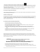
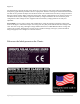
Dealer Information Screen For dealers‘ convenience the Classic has a display screen that can be modified to publicize the dealers‘ business information. This is helpful because the customer will know who to contact in case they want to report any problems regarding the product. This will also help to promote retailers‘ accessories that are compatible with the Classic. This screen is capable of 20 characters per row and four rows, for a total of 80 modifiable characters.
HyperVOC ™ Origins HyperVOC can be useful in overcoming an industry shortcoming in charging 48 volt battery‘s with standard panels. For example let‘s take a sample system with Solar World 165‘s that have a VOC of 44.1vdc. The industry has limited us to 2 of these panels in series making it hard to charge a 48vdc battery on hot summer days. With the Classic we designed in Hyper VOC to allow you to run 3 of these in series. 3 panels at 44.1vdc will give you a total VOC of 132.3vdc.
Technical information Table 6.
Specifications Mechanical 89 | P a g e
Default Battery charge set points The table below describes the default preset voltages for the different nominal battery voltages. This means that if you set the Classic from the QUICK SET Menu (see page 25) to a different battery voltage the Classic will take the default voltage set points. Note. If you manually adjust the absorb float or equalize voltage set point, and then nominal battery voltage is changed to a different nominal voltage, (e.g. from 24v to 12v or to 48v etc.
Warranty MidNite Solar's Classic comes with a standard 5 year warranty we will repair or replace the Classic at no charge to the consumer during this 5 year period End of Warranty tune up MidNite Solar offers a industry first Tune up / Extended Warranty. 6 months prior to the end of the warranty period Customers can ship their Classic back to MidNite Solar with a check for $125 dollars and we will replace any wearable items like the fans and the capacitors and in general tune the Classic up.
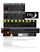
Figure 3.0 Aux 1 and Aux 2 Graphs/Jumpers Figure 3.0 shows the two Aux port terminals, with their respective polarities. These terminals are located at the bottom of the power board below the battery temperature jack. Use a mini flat head screw driver to tighten the screws. The jumpers are described in the section below.
Aux 1 Voltage-Time Relation (Relay/12v) Aux 1 Function Graph shows the relationship between voltage and time of AUX 1. (The axis labeled VOLTAGE could be battery, PV, wind input voltage, etc.
Table 6.
Classic Menu Map 95 | P a g e