
Unit installation


7
more
can then proceed with the installation of the quartz sleeves.
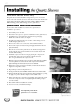
intermittent operation
Never operate the unit without water flow. Permanent
damage is caused to the UV lamps, electronic ballasts
and related components without water flow.
Operating the ultraviolet unit without water flow
through the chamber automatically voids the warranty.
If operated without water flow, the fluid within the
ultraviolet chamber will become hot causing the UV
lamps to lose effectiveness. The heat can permanently
damage the ultraviolet lamps, UV sensor, the lamp ballast
components and related instrumentation.
Should the unit be used for specific batch flow opera-
tions, it can be turned “On” and “Off” manually. Make
sure the unit is allowed to warm up for at least one
minute before use, and make sure the unit is turned
“Off” after each session. Do not exceed 3 on/off cycles
per 24 hour operation.
If you need help to determine the best method of operat-
ing your UV treatment unit under intermittent conditions,
contact your local representative or the factory.
An optional Temperature Safety Control Device is available
to prevent the overheating problems described above.
special piping requirements
for users of ultrapure water
Ultrapure water users have reported that over time,
exposure to ultraviolet light may photochemically
degrade nonmetallic piping materials, including most or
all fluoro-polymers, resulting in material breakdown
and/or structural failure.
Should your water application and piping material be so
classified, we recommend you install “UV light traps” to
isolate any such susceptible material from direct
exposure to the ultraviolet light. Install the UV light trap
to the inlet/outlet of the UV treatment chamber prior to
the connection of any nonmetallic materials. UV light
traps protect nonmetallic piping. Should you require any
additional assistance, please contact your local
Aquafine representative or the factory directly.
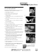
wiring the unit
Connect the liquid-tight flex conduit, which contains
the interconnecting wiring harness, into the remote electrical
enclosure through the liquid-tight connector which is
provided. Connect the wiring harness to the terminal block
starting with terminal block assembly A through terminal
block assembly B. (See Wiring Diagram in back pocket of
this manual.) Optional equipment connections are made on
terminal C. Terminal C blocks are included with optional
equipment.
Bring your incoming wiring to the 1/2-inch electrical knock-
out in the bottom of the remote electrical enclosure. Make
connections to terminal blocks G, N and L. Terminal block L
is “hot”; N is “neutral”; and G is the “ground”. Make sure
your electrical service matches the specifications on the
electrical name plate decal on your unit. Locate an “on/off”
switch near the unit so the current may be turned off for
servicing.
GROUNDINGGROUNDING
GROUNDINGGROUNDING
GROUNDING
IT IS IMPERATIVE THAT THE UNIT BE PROPERLY
GROUNDED FOR SAFE AND PROPER OPERATION.
Failure to properly ground the UV treatment unit automati-
cally voids all equipment warranty.
UV performance is line voltage sensitive. Line voltage
should be +5% of rating shown on the electrical nameplate
decal. Voltage outside these limits can reduce the perfor-
mance of the UV equipment.