
Unit installation


17
model S-254 UV optical sensor
option
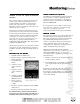
The optional S-254 UV optical sensor measures the
relative output of ultraviolet light within the UV
treatment chamber. Degradation of the UV lamps,
fouling of the quartz sleeves, water temperature
fluctuation and increased turbidity of the water will
all affect the sensor reading.
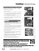
The UV meter assembly and instrumentation setpoint
potentiometers are located on the front of the electrical
enclosure. The peripheral alarm contacts are accessible
from the back side of the meter. A shielded signal cable
connects the sensor meter assembly to the sensor
probe. The sensor probe is located in the sensor port
fitting on the top of the UV treatment chamber in
Double-Ended, High-Temperature (HT) units and in the
endplate in Single Ended units.
All S-254 UV optical sensors are tested and preset at the
factory in free air. Setpoint adjustments are required at
installation and after each subsequent lamp changeout
cycle.
SETTING THE UV METERSETTING THE UV METER
SETTING THE UV METERSETTING THE UV METER
SETTING THE UV METER
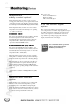
1. Gradually start the normal flow rate.
2. Bring the unit up to normal operating pressure.
3. Turn the UV lamps on
for a minimum of 15
minutes.
4. Adjust the potenti-
ometer sensitivity to
100%.
5. Adjust the potenti-
ometer sensitivity to
50%.
6. Adjust the potentiom-
eter alarm until the red
LED barely comes on.
7. Set the potentiom-
eter sensitivity back
to 100%.
8. Turn the potentiometer sensitivity to 50%; the red LED
should come on.
9. Turn the potentiometer sensitivity back to 100%.
Re-calibration must be performed after the first 100
hours of operation on new UV lamps, both at the time of
installation and each time the UV lamps are replaced.
ALARM CONTALARM CONT
ALARM CONTALARM CONT
ALARM CONT
AA
AA
A
CTS (CTS (
CTS (CTS (
CTS (
optionaloptional
optionaloptional
optional
))
))
)
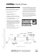
Normally Closed and Normally Open alarm contacts are
also provided for use with user-supplied peripheral
equipment, such as remote alarms or solenoid valves.
Dry relay contacts are rated as follows: 0.52 AMP 120
VAC., 0.25 AMP 240 VAC
If your application requires higher contact ratings,
use a slave relay. Connection of peripheral equip-
ment is the responsibility of the user.
See the wiring schematic in back pocket of this manual
SENSOR ALARMSENSOR ALARM
SENSOR ALARMSENSOR ALARM
SENSOR ALARM
The S-254 UV optical sensor provides information about
the relative amount of UV passing through the water.
The reading is affected by quartz sleeve fouling and/or
the germicidal lamp efficiency. The UV sensor is
sensitive to, and reflects changes in, UV transmission
when a substantial change occurs in the normal
operating flow rate, temperature, operating pressure, or
quality of the fluid flowing in the system.
When the UV intensity falls below the minimum
standard due to any of the above conditions, the sensor
alarm light (red LED) will come “on” and corrective
action must be taken to optimize the performance of the
UV treatment unit.
1. Examine your system for any significant changes in
normal operating conditions.
2. Check if all UV lamps are electrically operating and/
or need replacement. Verify the quartz sleeves are
clean.
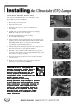
If quartz sleeve fouling has caused the optical sensor
alarm to activate, the quartz sleeves must be cleaned. At
the same time, you must clean the sensor probe quartz
window. Please find this information in the maintenance
section of this manual.
S-254 UV Optical Sensor