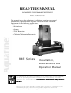
READ THIS MANUAL PLEASE KEEP FOR PERMANENT REFERENCE Part No.
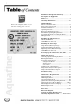
Installation and Operational Safety ................. 3 Description of Equipment RBE Series ............................................................ 4 Warranty Information ....................................4-5 Refer to this nameplate sticker on your unit when ordering parts or service. Unit Installation Where to Install the Unit ....................................... 6 How to Protect Your Unit ..................................... 6 Hot Water Sanitization .........................................
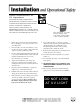
Safety requirements for UV equipment The following safety requirements relate directly to operator safety. Please review with all appropriate personnel to ensure continuous compliance. These safety requirements are MANDATORY. Failure to carefully follow these requirements can cause injury to the operator and damage the UV unit. 1. Release the pressure in the UV treatment chamber before attempting to remove the protective covers and sealing items. 2.
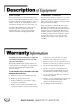
RBE series treatment chamber The models in this series contain all electrical components in a Remote Electrical Enclosure. This is ideal for applications where the treatment chamber is outdoors or subject to washdown, etc. All electrical service and instrument monitoring can be done at the remote site. The UV treatment chamber is comprised of one or more multi-lamp cylinders. On either end are gasketed end plates which contain the stainless steel nipples and the lamp socket retainer assemblies.
more WARRANTY Aquafine equipment is guaranteed to be free from defects in materials and workmanship (excluding ultraviolet lamps) for a period of one year from the date of purchase. Any part suspected of being defective should be returned prepaid to Aquafine Corporation. If upon our inspection, the part(s) proves to be defective, it will be replaced or repaired (our option) and returned to sender prepaid.
where to install the unit Install the UV treatment unit in a horizontal position in a sheltered area with ample ventilation. Ambient temperatures surrounding the unit should be between 35oF (2oC) and 110oF (43oC). For operation below 50oF contact Aquafine. Should your requirements differ, contact the factory for assistance.
more can then proceed with the installation of the quartz sleeves. wiring the unit intermittent operation Connect the liquid-tight flex conduit, which contains the interconnecting wiring harness, into the remote electrical enclosure through the liquid-tight connector which is provided. Connect the wiring harness to the terminal block starting with terminal block assembly A through terminal block assembly B. (See Wiring Diagram in back pocket of this manual.
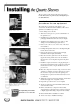
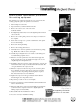
The procedures on this and the following page apply to Double-Ended (DE), Single-Ended (SE) and High Temperature (HT) RBE units. quartz sleeve installation procedures for new equipment The quartz sleeves designed for this unit are open on both ends. For first time unit installations, follow these quartz sleeve installation procedures: Remove socket covers 1. Turn off all power to the unit. 2. Wear clean cotton gloves to prevent contamination of the quartz sleeves. 3.
more quartz sleeve replacement procedures for existing equipment The quartz sleeves designed for this unit are open on both ends. For existing equipment, replace the quartz sleeves as follows: 1. Turn off all power to the unit. 2. Depressurize the system and drain the UV unit. 3. Remove the socket covers on the ends of the treatment chamber. Remove socket covers 4. For High-Temperature units, remove the alignment plate from both ends of the unit. 5.
USD-RBE Series units only The quartz sleeves for this unit utilize a design that is open on one end and closed on the other end. The closed end of the tube is inserted into the threaded nipple and then through the baffle system in the chamber. Within the baffle, Teflon bushings provide additional support to the quartz sleeves. Q U AR TZ SLEEVE INST ALLA TION PR OCEDURES ARTZ INSTALLA ALLATION PROCEDURES For first time unit installations, follow these quartz sleeve installation procedures: 1.
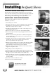
single-ended lamp design for units manufactured after January 1, 1999 Once it has been verified that there are no leaks in the system, the UV lamps are ready for installation. 1. Remove all power to the UV unit. Insert the lamp into quartz sleeve 2. Depressurize the system. 3. Wear clean cotton gloves to prevent contamination of the UV lamps. 4. Carefully remove each UV lamp from the factory packaging. Handle these with care as they are fragile. 5. Visually inspect all lamps for cracks or damage.
more double-ended lamp design for units manufactured prior to Jan. 1, 1999 1. Remove all power to the UV unit. 2. Depressurize the system. 3. Wear clean cotton gloves to prevent contamination of the UV lamps. 4. Insert one UV lamp into each open quartz sleeve and push it about 2”-3” (51-76mm) out beyond the left compression nut, so as to be able to hold the lamp with your right hand. 5. Unscrew and pull back the retainer cap from the rubber lamp socket. Insert Lamp Base into Quartz Sleeve 6.
more high-temperature (HT) units Once it has been verified that there are no leaks in the system, the UV lamps are ready for installation. 1. Remove all power to the UV unit. 2. Depressurize the system. 3. Wear clean cotton gloves to prevent contamination of the lamps. 4. Carefully remove each UV lamp from the factory packaging. Handle these with care as they are fragile. 9.
USD-RBE Series units only Once it has been verified that there are no leaks in the system, the UV lamps are ready for installation. 1. Remove all power to the UV unit. 2. Depressurize the system. 3. Wear clean cotton gloves to prevent contamination of the UV lamps. Insert the lamp in a level, horizontal position. 4. Carefully remove each UV lamp from the factory packaging. Handle these with care as they are fragile. 5. Visually inspect all lamps for cracks or damage. Do not install damaged lamps. 6.
prior to turning on the UV unit, the following must be verified: • With water flowing through the system, ensure that there are no system leaks and no piping connection leaks. • All earth ground connections are properly made. • All lamp connections are properly made. • The socket covers are secured to both ends of the UV treatment unit. 1. Verify that all incoming power conductors, including the ground conductor, are properly terminated. 2. Turn on the electrical power to the UV unit. 3.
UV lamp operational display panel To verify that all the UV lamps are operating properly, your UV treatment unit has been provided with a UV Lamp Operational Display Panel. The panel consists of as many LED indicators as there are ultraviolet lamps. Each LED indicator is electrically connected to the lamp circuitry of a specific UV lamp. The LED indicators are intended to operate “on” when the UV lamps are also turned “on”.
model S-254 UV optical sensor option The optional S-254 UV optical sensor measures the relative output of ultraviolet light within the UV treatment chamber. Degradation of the UV lamps, fouling of the quartz sleeves, water temperature fluctuation and increased turbidity of the water will all affect the sensor reading. The UV meter assembly and instrumentation setpoint potentiometers are located on the front of the electrical enclosure.
more temperature safety control option* The Temperature Safety Control consists of a heatsensing probe. This device protects against inadvertent overheating inside the UV chamber, which can damage the UV lamps and the ballast/LED Display Panel circuitry. The Temperature Safety Control senses raised water temperature and assumes the UV lamps are operating “on” with no water flow.
using the LED display If an LED bulb does not light after you replace a UV lamp, you need to verify the electrical output of the ballast connected to that specific UV lamp. This is done by testing the ballast open circuit voltage. This should be done by an electrician or qualified facilities personnel. Follow these recommended procedures: 1. Turn power “off” to the UV unit. UV Lamp Operational Display Panel 2. Remove the socket cover. 3.
cleaning the unit The exterior surfaces of the Aquafine UV unit should be kept clean as part of routine maintenance. Use a soft cloth with soap and water or any commercial stainless steel cleaner. Avoid scratching the Lexan instrument window. Recent studies have shown that degradation of the quartz sleeve from continuous exposure to UV reduces the amount of UV radiation transmitted into the water stream.
more 6. Replace the probe and the coaxial cable. 7. Turn the power “on” and resume operation. Whenever new lamps have been installed, follow all resetting instructions. measuring performance Every UV treatment unit should be tested periodically to verify actual efficiency.
more ballast replacement Ballast replacement is not part of the UV unit’s routine maintenance. However, in the event that a ballast needs to be replaced, the following procedure should be followed: Ballast connectors 1. Power down the UV unit by turning the unit isolator switch, if installed, to the “OFF” position. If not, ensure that power to the unit is removed by opening the switch or breaker upstream of the UV unit. 2. Locate the old ballast to be replaced.
Refer to this nameplate decal on your unit when ordering parts or service. general part description ................................... part number GENERAL 1. O-rings - EPDM ......................................................................................................... 4253 2. O-rings - Silicone ...................................................................................................... 12967 3. O-rings - Viton ..................................................................
more double-ended units cont. ............................................. part number 13. UV Lamps DE Standard 185-Blue TOC Reduction Applications Size: 30” Length ............................................................................................................. 3087 Size: 60” Length ............................................................................................................. 3095 14.
single-ended units cont. .............................................. part number 28. UV Lamps SE Validated 185-Yellow TOC Reduction Applications Size: 30” Length ........................................................................................................... 18977-7 Size: 60” Length ........................................................................................................... 18977-8 29.
more single-ended units cont. .............................................. part number HIGH-TEMPERA TURE (HT) UNITS HIGH-TEMPERATURE 41. Lamp Socket .................................................................................................................. 15596 42. Lamp Socket Assembly for HT unit .............................................................................. 13899 43.