
Instruction manual


Upstream Instruction Manual
Released on 1-May-14 – R800001Q Page 19 UV Pure Technologies Inc. © 2014
Step 3: Open blower housing panel and remove screw that secures it.
Step 4: Gently pull out blower housing and blower allowing connector and wire to
follow.
Step 5: Remove knockout & install conduit / external wiring up to circuit board
and terminate. Wiring may be secured internally to standoffs but allow enough
slack to allow front panel to open.
Step 6: Test opening of front panel to ensure newly installed wires do not restrict
movement.
Step 7: Replace blower and blower housing and allow connector & wire back to
the circuit board. Secure with screw. Ensure wires do not obstruct blower.
Step 8: Plug in blower connector to J6.
Step 9: Close ballast enclosure door and secure with screw.
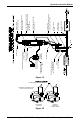
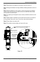
GROUND
POWER INPUT
MOTOR, P. VALVE
UV BLOWER
AIR THERMISTOR
CB FAN
REMOTE S/S 0
REMOTE S/S 1
DRY CONTACT NC
GROUND
DRY CONTACT NO
DRY CONTACT COMM
& W. THERMISTOR
BLUE
YELLOW
RED
YELLOW
SHUTOFF VALVE
TB1
J2
J6 J14 J7
TB3D
TB3C
TB3B
TB3A
J1
F1
DO NOT REPLACE
FUSE IF IT BLOWS.
A BLOWN FUSE
IMPLIES MAJOR PCB
FAULT. REPLACE
ENTIRE PCB.
(MARKED RED)
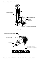
F1
J1
TB3A
TB3B
TB3C
TB3D
J7J14J6
J2
TB1
SHUTOFF VALVE
YELLOW
RED
YELLOW
BLUE
& W. THERMISTOR
DRY CONTACT COMM
DRY CONTACT NO
GROUND
DRY CONTACT NC
REMOTE S/S 1 (-)
REMOTE S/S 0 (+)
CB FAN
AIR THERMISTOR
UV BLOWER
MOTOR, P. VALVE
POWER INPUT
GROUND
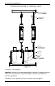
VIEW WITH BALLAST ENCLOSURE DOOR OPEN
UNPLUG UNIT BEFORE OPENING DOOR
CIRCUIT BOARD (PCB)
SHUTOFF (INTERLOCK)
SWITCH BEHIND PCB
(SEE FIGURE 1H)
Figure 1G