
Instruction manual


Upstream Instruction Manual
Released on 1-May-14 – R800001Q Page 15 UV Pure Technologies Inc. © 2014
hose excessively. Tighten securely.
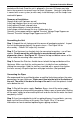
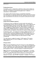
Step 6: Connect the purge valve to a drain using the flexible tubing provided. Cut
the end of tubing square and insert into the push-in fitting. The tubing can be run
down the right hand side of the unit within the recess provided – the plastic cover
may be removed to insert tube. The tubing should be secured to the wall or floor
to prevent it from moving during purging cycle. If the pressure tank (water
reservoir) is located downstream of the unit, the purge valve must be relocated. A
Purge Valve Relocation Kit R500003 (sold separately) is required to have the
water flow through the quartz. See Figure 1C
Step 7: Caution: Do not allow the inside of the unit to get wet. Before
opening the water supply, double check all connections and cover the top of the
unit with a rag or some plastic to prevent water entry. Ensure front panel is
closed. Close any faucets you opened in Step 1 and then slowly turn on the
water supply to check for leaks. If leaks exist, investigate the cause and repair.
Caution: Do not connect the unit to electrical power until the piping and unit are
free of water leaks. The optional solenoid valve can be placed into manual mode
to allow water to enter the unit. Switch back to automatic mode when done.
Step 8: Once the system is checked for leaks under full system pressure, install
pipe insulation on the outlet hose and piping to prevent condensation from falling
onto or into the unit.
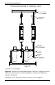
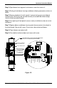
Parallel Installation
When more than one unit is installed in parallel (flow split between units), the
units must be installed with manual shutoff valves both upstream and
downstream of each unit. This allows one unit to be serviced without interrupting
the flow to the other units. Another requirement is the installation of a check valve
downstream of the unit (after the unit). This will prevent the backflow of water to a
unit. See Figure 1F.
Plugging in the Upstream
Step 1: Ensure that the front panel of the unit is closed and the unit is securely
fastened to the wall. (Note: You should not open the front panel unless the unit
has been unplugged).
Caution: Do not operate unit dry. There must be water in the treatment
chamber to prevent damage to internal components.
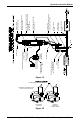
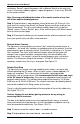
Step 2: Plug the female end of the power cord into the power entry module
located on the left side of the front panel. The power cord must be removed
before front panel can be opened. See Figure 1B or 1C. Plug the male end of the
power cord into the Transient Voltage Surge Suppressor supplied. Plug the
Transient Voltage Surge Suppressor into a GFCI. Flip the switch on the Transient
Voltage Surge Suppressor to ON position.