
Instruction manual


Upstream Instruction Manual
Released on 1-May-14 – R800001Q Page 12 UV Pure Technologies Inc. © 2014
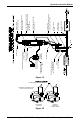
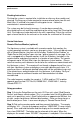
SUPPLIED FOR NORTH
AMERICAN MARKETS
ONLY
POWER CORD ENTRY &
LOCATION OF SERIAL NUMBER
DEVICES
UPSTREAM UNIT
MOUNTED VERTICAL
AGAINST A WALL
PURGE VALVE
(SEE FIG. 4B
FOR DETAILS)
DRAIN
OPTIONAL SOLENOID VALVE
(UNI-DIRECTIONAL)
(TEST VALVE MONTHLY)
GFCI
115VAC 50/60Hz OR
100-240VAC 50/60Hz
OPTIONAL
DRAIN VALVE
MANUAL
SHUTOFF VALVE
OPTIONAL BYPASS
VALVES
FLEXIBLE HOSE
FLEXIBLE HOSE
PIPE INSULATION
(MUST BE INSTALLED)
COPPER TUBING OR EQUIVALENT
OR HIGH TEMPERATURE PLASTIC
SUCH AS PEX
(DO NOT USE PVC)
PURGE VALVE
DISCHARGE LINE
(TO BE SECURED TO WALL)
PURGE VALVE
CONNECTION FOR OPTIONAL
SOLENOID VALVE
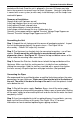
ON/RESET
POWER
OFF
TRANSIENT
VOLTAGE
SUPPRESSOR
Figure 1B
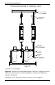
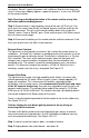
Step 3: Connect the optional solenoid valve to the plumbing just upstream
(before) the unit. Note the solenoid valve ensures that should the system fail, due
to power loss, color in the water or low UV lamp output, the system will fail in
safe mode and shut down the flow of water to your tap.
The direction of flow through the valve is important – verify flow direction with
label on the valve. Caution: over tightening a metal fitting into the valve will
cause it to crack. Do not over tighten. Keep the coil of the valve pointing
upward (to prevent water from dripping on it). Water will not flow backwards
through the valve. See Figure 1D
If you did not purchase the optional solenoid valve please move to Step 4 (b)