
Instruction manual


Upstream Instruction Manual
Released on 1-May-14 – R800001Q Page 11 UV Pure Technologies Inc. © 2014
treated and flushed. Once the unit is plugged in, the new UV lamps may take
from a few moments to several hours to reach full power. Having a Lamp Alarm
is normal with a new system (or with newly installed lamps) until the lamps have
reached full power.
Summary of Installation:
Unpack and install Upstream on wall
Install top & bottom hose to unit and to plumbing
Install optional Shutoff solenoid valve
Install optional bypass & drain plumbing
Install purge valve discharge line to a suitable drain line
Connect system power cord to supplied Transient Voltage Surge Suppressor
Connect Transient Voltage Surge Suppressor to GFCI
Assembling the Unit
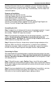
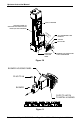
Step 1: Unpack the unit, being careful to remove all packaging material. Inspect
the unit for damage particularly the quartz sleeve – See Figure 4A for
disassembly. Check if UV lamps fully inserted.
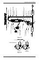
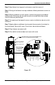
Step 2: The Upstream has keyhole slots for convenient mounting – use all four
mounts. Do not mount the unit directly to an outside wall; mount on
plywood or shims – See Figure 1E. Remove the top and bottom covers of the
unit to make the mounting holes accessible.
Step 3: Connect the Stainless flexible hoses to both the top and bottom of the
Upstream. Make sure that the sealing washer is inside the hose end before
making the connection. Hold the stainless manifold with a wrench then tighten
the hose securely. Wrap the top hose with pipe insulation. (Not provided)
Connecting the Pipes
We recommend that a qualified plumber or certified technician perform the water
connections for your Upstream. Water must flow into the inlet at the bottom of
the unit. The outlet is located at the top of the unit. Install the optional shutoff
valve before the unit.
Step 1: Shut off the water supply. Caution: Always turn off the water supply
before modifying or disconnecting any piping. Always open a faucet after shutting
off the water supply to relieve water pressure and ensure that the water has been
completely shut off.
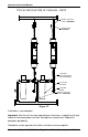
Step 2: If you have decided to install an optional bypass line and drain, you may
begin to install these fittings at this point. See Figure 1B or 1C for more
information on how to connect optional bypass piping and drain.