® UV Pure Technologies Inc. ULT RAVI O L ET WAT ER PURI F I CAT IO N SYST EM INSTRUCTION MANUAL MODEL: VOLTAGE: SERIAL #: Certified to IEC PUBLICATION 60335.
Upstream Instruction Manual INSTRUCTION MANUAL Copyright UV Pure Technologies Inc. 2014 All rights reserved. No part of this document may be photocopied, reproduced, transmitted, or translated to another language without the prior written consent of UV Pure Technologies Inc. UV Pure®, Hallett®, Upstream ® ,Crossfire Technology® are registered trademarks of UV Pure Technologies Inc.
Upstream Instruction Manual 1. ABOUT THE UPSTREAM The Upstream and the Hallett systems, manufactured by UV Pure Technologies, are the world’s only ultraviolet water purification device with patented Crossfire Technology. Patented in US 6,707,048, Canada 2,463,503, Australia 2,002,333,084, Mexico 248805 Patent Pending in Japan, UK, Europe, & Eurasia UV Pure’s Upstream UV systems employ revolutionary Crossfire Technology that is self-cleaning, self-monitoring, and fail-safe.
Upstream Instruction Manual stainless steel hoses with Female Iron Pipe (FIP) connections for quick and simple installation. The Upstream has a smart display: The operator interface allows for unprecedented access to information such as lamp lifetime, message history and UV intensity display. The Upstream can show remote status: Be alerted to any change in system status immediately in any room with the optional Remote Monitor.
Upstream Instruction Manual 1. ABOUT THE UPSTREAM ................................................................................. 3 2. INSTALLATION INSTRUCTIONS .......................................................................... 6 Before Beginning Installation ..................................................................... 6 Water Conditions - Pre-treatment Parameters ............................................ 6 Safety Information ...........................................................
Upstream Instruction Manual 2. INSTALLATION INSTRUCTIONS Before Beginning Installation Water Conditions - Pre-treatment Parameters Note this section is designed to ensure the optimal performance of your Upstream system. Please review the following pre-treatment parameters prior to installation. If any specifications are of concern or unclear please contact your water treatment dealer or specialist.
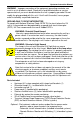
Upstream Instruction Manual WARNING - Improper connection of the equipment-grounding conductor can result in a risk of electric shock. Check with a qualified electrician or service representative if you are in doubt whether the unit is properly grounded. Do not modify the plug provided with this unit; if it will not fit the outlet, have a proper outlet installed by a qualified electrician.
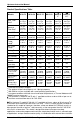
Upstream Instruction Manual Product Specifications Table NC10-75 NC10-50 NC15-75 NC15-50 NC30-75 1" NC30-75 1.5" Max. Flow 1 Rate 11 gpm 41 L/min 3 2.4 m /hr 11 gpm 41 L/min 3 2.4 m /hr 16.5 gpm 62 L/min 3 3.7 m /hr 14.6 gpm 55 L/min 3 3.3 m /hr 28.5 gpm 108 L/min 3 6.47 m /hr 28.5 gpm 108 L/min 3 6.47 m /hr Nominal 1 Flow Rate 10 gpm 38 L/min 3 2.3 m /hr 10 gpm 38 L/min 3 2.3 m /hr 15 gpm 57 L/min 3 3.4 m /hr 13.2 gpm 50 L/min 3 3.0 m /hr 26.4 gpm 100 L/min 3 6 m /hr 26.
Upstream Instruction Manual Other Materials Needed The Upstream requires four # 12 to 1/4” diameter fasteners (not provided) to mount to a wall. It also requires male NPT fittings for the hose connections and also for the optional solenoid valve (1”or 1.5”). The Upstream unit requires a drain for purge valve discharge line. These fittings, pipe insulation, and any piping compatible with the plumbing should be on hand before you begin installation.
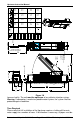
32.27" [820] 39.75" [1010] 1 DSi30_112" NC30-75_112" NCi30-75_112" DS30_112" DS30_1" DSi30_1" NC15-50 NCi15-50 NC30-75_1" NCi30-75_1" 1" 12" 39.75" [1010] 27.63" [702] 27.75" [705] 32.27" [820] 27.63" [702] 27.75" [705] 28.27" [718] 23.75" [603] 35.75" [908] 1" DS15 DSi15 NCi15-75 NCi10-50 DSi10 NC15-75 NC10-50 NCi10-75 DS10 WIPER NC10-75 1" NPT MALE 32.00" [813] 25" [635] 21.38" [543] 20.00" [508] 24.52" [623] Upstream Instruction Manual TO MOUNT USE #12 OR 4" DIA.
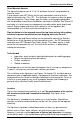
Upstream Instruction Manual treated and flushed. Once the unit is plugged in, the new UV lamps may take from a few moments to several hours to reach full power. Having a Lamp Alarm is normal with a new system (or with newly installed lamps) until the lamps have reached full power.
DEVICES OPTIONAL DRAIN VALVE MANUAL SHUTOFF VALVE OPTIONAL SOLENOID VALVE (UNI-DIRECTIONAL) (TEST VALVE MONTHLY) FLEXIBLE HOSE POWER CORD ENTRY & LOCATION OF SERIAL NUMBER GFCI 115VAC 50/60Hz OR 100-240VAC 50/60Hz PURGE VALVE (SEE FIG.
F LO W AUTOMATIC POSITION Released on 1-May-14 – R800001Q Page 13 FLEXIBLE HOSE DEVICES MANUAL SHUTOFF VALVE O FF OPTIONAL SOLENOID VALVE (UNI-DIRECTIONAL) (TEST VALVE MONTHLY) O N/ RESE T TRANSIENT VOLTAGE SUPPRESSOR PO W ER SUPPLIED FOR NORTH AMERICAN MARKETS ONLY GFCI 115VAC 50/60Hz OR 100-240VAC 50/60Hz POWER CORD ENTRY & LOCATION OF S/N UPSTREAM UNIT MOUNTED VERTICAL AGAINST A WALL FLEXIBLE HOSE DRAIN OPTIONAL BYPASS VALVES PURGE VALVE DISCHARGE LINE OPTIONAL DRAIN VALVE PURGE VALVE
Upstream Instruction Manual MOUNT UNIT FLAT AGAINST A BOARD OR SHIM OR INCORRECT CORRECT Figure 1E Step 4: a) Connect the optional solenoid valve to the Stainless flexible hose attached to the bottom of the Upstream. Do not bend the hose excessively. Make sure the sealing washer is inside the end of the hose before making the connection. The optional solenoid valve plugs into the right hand side of the unit where a port is provided.
Upstream Instruction Manual hose excessively. Tighten securely. Step 6: Connect the purge valve to a drain using the flexible tubing provided. Cut the end of tubing square and insert into the push-in fitting. The tubing can be run down the right hand side of the unit within the recess provided – the plastic cover may be removed to insert tube. The tubing should be secured to the wall or floor to prevent it from moving during purging cycle.
Upstream Instruction Manual TYPICAL INSTALLATION OF PARALLEL UNITS MANUAL SHUTOFF VALVE - ESSENTIAL CHECK VALVE ESSENTIAL OPTIONAL SOLENOID VALVE (RECOMMENDED) 20" FILTER HOUSING OPTIONAL DRAIN MANUAL SHUTOFF VALVE - ESSENTIAL Figure 1F Installation is now complete. Important: after the unit has been operating for a few hours, unplug the unit and check all hose connections for leaks (the top hose in particular). Repeat this procedure periodically.
Upstream Instruction Manual performance. Flushing Instructions Flushing the system is required after installation or after any disassembly and cleaning. Flushing may also be required to remove colored water from the unit. Most filters (if installed) also require flushing prior to use – follow the manufacturer’s recommendations. The system may be flushed in two ways. It can be done manually by disassembling the unit and filling and draining the unit by hand (see Cleaning the Unit).
Upstream Instruction Manual not display “Bound”, repeat the process with a different Bind # on the main unit (even if a message suddenly appears, repeat the process). It must say “BOUND” on the remote monitor. Note: Pressing and holding the button of the remote monitor at any time will initiate another binding process. Step 3: Syncronization is now complete, return to the main UV Pure unit. You must return the screen from Bind # to “Bound” by pressing Enter and then the Down Arrow button.
Upstream Instruction Manual Step 3: Open blower housing panel and remove screw that secures it. Step 4: Gently pull out blower housing and blower allowing connector and wire to follow. Step 5: Remove knockout & install conduit / external wiring up to circuit board and terminate. Wiring may be secured internally to standoffs but allow enough slack to allow front panel to open. Step 6: Test opening of front panel to ensure newly installed wires do not restrict movement.
Upstream Instruction Manual CIRCUIT BOARD LOOSEN SCREW TO OPEN BALLAST ENCLOSURE DOOR (DO NOT REMOVE) VI EW A TILT FORWARD THEN REMOVE SCREW AIR FILTER KNOCKOUT LOCATED HERE BLOWER HOUSING PANEL FLIPS DOWNWARD Figure 1H BLOWER HOUSING PANEL PLUG TO J6 BLOWER CLIPS TO LATCH TO METAL HOUSING Figure 1I Released on 1-May-14 – R800001Q Page 20 UV Pure Technologies Inc.
Upstream Instruction Manual 3. OPERATING INSTRUCTIONS The Upstream applies advanced Crossfire Technology, yet is simple to operate. The automatic quartz cleaning technology has been designed to reduce, and in most cases, eliminate the periodic shutdowns necessary to inspect the cleanliness of the quartz.
Upstream Instruction Manual Amber Light – situated in the middle, an illuminated amber light may indicate the Initial Set-up process has begun or a warning of some condition that, if not addressed, could impact the Upstream’s performance. Warnings should be addressed as soon as possible. Warnings are accompanied with a single beep, messages and troubleshooting tips on the LCD display.
Upstream Instruction Manual are reaching full power. The green light will flash and the amber light will be on solid. This process may last 24 hours. When the Initial Set-up process is complete, a solid green light appears and the message “Unit Treating” will be displayed. The solenoid valve (optional) will be allowed to open during the Initial Set-up process. This is the normal operating mode of the unit.
Upstream Instruction Manual UV Pure Technologies’ UV water purification system models are designed to operate within normal power grid specifications (voltages and frequencies), worldwide. However power spikes, surges and brownouts are a common occurrence in all countries. When that happens, line voltages may fluctuate outside the systems’ operating specifications.
Upstream Instruction Manual The accepted practice for sanitizing the household or facility plumbing involves adding 50 ppm chlorine from bleach for 12 hours and then flushing. This can be achieved by doing the following: Step 1: Turn off the unit by unplugging it. Step 2: Shut off the water supply and relieve the water pressure by opening a faucet. Step 3: Remove the filter from its housing and fill the housing with bleach.
Upstream Instruction Manual should be corrected to return the unit to normal operation and have the water flow again. When an alarm occurs, navigate to the “Alarm Condition Exists” screen by pressing LEFT arrow several times. Next press RIGHT arrow to silence the audio alarm and review which alarm condition exists. The menu will bring you to Alarms and Troubleshooting section for assistance with current condition. The Message History can be reviewed to examine other recent events.
Upstream Instruction Manual M AIN M ENU When a unit is new or the UV lamps have been replaced and the Lifetime counter has been reset, the system begins an Initial Set-up process which may last 24hrs. Continue to operate unit. Self Diagnostics INITIAL SET-UP MAY TAKE 24HRS..
Upstream Instruction Manual SERVICE M ENU Service Menu Enable Wiper AUTO Enable Wiper AUTO/ON/OFF Enable Purge Valve AUTO Enable Purge Valve AUTO/ON/OFF Shutoff Valve AUTO Shutoff Valve AUTO/ON/OFF Temperature Readings Water Temp. deg C deg F Enabling/Disabling Wiper or Valves is temporary. Items return to AUTO mode after 10 minutes. UV Air Temp. deg C deg F CB Air Temp. deg C deg F The Audio Alarm or beeper, can be temporarily or permanently disabled.
Upstream Instruction Manual SETUP M ENU Setup Menu NC 10-75 Language English English/French Remote StartStop Disabled Remote StartStop Disable/Enable Shutoff Valve Not Installed Not Installed / Installed Unit Configuration Enter Password ###### Language Shutoff Valve Remote Device BIND # Bind Remote Device Remote Device BOUND ALARMS & TROUBLESHOOTING M ENU This column represents all possible reasons for the fault.
Upstream Instruction Manual ALARMS & TROUBLESHOOTING M ENU (CONT’D) This column represents all possible reasons for the fault.
Upstream Instruction Manual M ESSAGE HISTORY M ENU NEW Message History Alarm, Warning or Status messages Last 50 messages Message # Time #### hrs Time based on lamp counter Net UVT UV Int. XXX% XXX% Values recorded when event occurred 5. M AINTENANCE Test Shutoff Valve Monthly The Optional Solenoid Shutoff valve should be tested monthly to confirm it opens and closes. Unplug valve from unit to confirm water stops flowing. Plug the valve in again to confirm water continues to flow.
Upstream Instruction Manual NOTE: Resetting the Lamp Lifetime counter will clear the Message History, Lamp Starts counter and Power Ups counter. If this information is required, review it first before proceeding to Step 1. NOTE: DO NOT TWIST/TURN THE LAMPS WHILE PINS ARE ENGAGED UV www.uvpure.
Upstream Instruction Manual Up or Down key to select YES and then press Enter. The lamp hours will reset to 9000 and the unit will turn off the lamps automatically. This will close the solenoid valve (optional) and temporarily shut off the water supply. Unplug power cord from left hand side of unit. Step 2: Remove the top cover by pulling each side of the plastic top cover outward from the unit. This will reveal the two wing nuts that secure the front panel in place.
Upstream Instruction Manual Step 3: Place a bucket under the unit to collect the water. Step 4: Open a faucet downstream of the unit. Step 5: If you have installed the optional drain valve, open the drain valve. If you do not have an optional drain valve, disconnect the Stainless flexible hose below the unit and allow the system to drain for a few minutes. Step 6: When draining is complete, close the drain valve or reconnect the flexible hose. Step 7: Close any faucets that were previously opened.
Upstream Instruction Manual PULL OUTWARDS AND LIFT REMOVE TOP COVER LOOSEN WING NUT QUARTZ Figure 4A In-place cleaning Your Upstream is equipped with a self-cleaning wiper that (in normal operating circumstances) maintains the quartz, and is engineered to ensure years of full disinfection. However, there are rare instances where water chemistry requires some manual quartz cleaning as well. This procedure will clean the quartz without its removal from the unit.
Upstream Instruction Manual 8 17 2 13 14B 1 7 17 5 3 4 12 17 6 11 16 10 16 17 18 19 Flow Restrictor 15 14A 13 9 20 8 17 Figure 4B – Upstream Released on 1-May-14 – R800001Q Page 36 UV Pure Technologies Inc.
Upstream Instruction Manual Upstream Spare Parts List Item No. Part Name NC10-75 NC10-50 NC15-75 NC15-50 NC30-75 NC30-75 1” 1.
Upstream Instruction Manual *Do not replace the fuse in the unit if it blows. A blown fuse indicates major circuit board fault. Replace entire circuit board. Inspect lamps-replace if discolored. Step 4: Disconnect the top hose from the plumbing side (not the unit side but other end). Step 5: Add about 2 oz. (60cc) of cleaning solution to the top hose. The cleaning solution can be a citric acid, vinegar or other non-hazardous solutions. Any solution used should be thoroughly rinsed out afterwards.
Upstream Instruction Manual DISCONNECT FLEX. HOSE REMOVE & SUPPORT TOP QUARTZ SEAL ASSEMBLY REMOVE WIPER ASSY. BY ROTATING IT COUNTERCLOCKWISE AS YOU LIFT DISCONNECT 1/4" PURGE VALVE DRAIN CUT WIRE TIE WRAP WHEN NECESSARY MOTOR MOTOR PURGE VALVE PURGE VALVE THERMISTOR THERMISTOR WIRES Figure 4C Use a 7/16” (11mm) wrench to remove the four nuts in an alternating pattern (top left, bottom right, bottom left, then top right).
Upstream Instruction Manual REMOVE TOP O-RING LIFT QUARTZ SLEEVE OUT OF THE UNIT REMOVE & SUPPORT TOP QUARTZ SEAL ASSEMBLY REMOVE BOTTOM O-RING REMOVE BOTTOM QUARTZ SEAL ASSY. DISCONNECT FLEX. HOSE REMOVE COVER: PULL OUTWARDS AND DOWN Figure 4D Step 2: If the quartz is still dirty, use a scale remover such as CLR or Lime Away and apply it to the inside of the quartz sleeve. Citric acid, available at a drug store, can also be used. Always flush with clean water afterwards.
Upstream Instruction Manual pulling the plastic tabs of the cover out and down and then undoing the four nuts in an alternating pattern (top left, bottom right, bottom left, then top right). Support the quartz sleeve as you remove this item. Step 6: Remove the quartz sleeve by removing the top and bottom O rings. Lift the quartz sleeve out of the unit. Step 7: Install the new quartz sleeve into the unit and center it vertically. Be careful not to chip the ends.
Upstream Instruction Manual HOLE ON END OF WIPER SHAFT MUST BE ON TOP ALIGN HOLE IN SHAFT ADAPTER WITH THE WIPER SHAFT Figure 4E Replacement Parts Use only genuine UV Pure Technologies’ parts when servicing your Upstream disinfection system. Failure to use genuine UV Pure Technologies’ replacement parts will void the factory warranty, and any laboratory validation and/or certification for water safety and system operating performance. Figure 4B shows a complete list of original factory parts.
Upstream Instruction Manual 6. SERVICE RECORD SHEET Record lamp replacement dates and events in the space provided below. Date (MMM/DD/YYYY) Action System Installed Released on 1-May-14 – R800001Q Page 43 UV Pure Technologies Inc.
Upstream Instruction Manual 7. UV PURE TECHNOLOGIES LIMITED WARRANTY Limited Warranty for UV Pure Technologies’® water purification systems and peripheral parts purchased in Canada, the United States, Australia and New Zealand. What this warranty covers: Defects in materials and workmanship in Products and Parts manufactured by UV Pure Technologies Inc.
Upstream Instruction Manual Who is covered: This Limited Warranty extends to you only if you are the FIRST END-USER PURCHASER and with respect to the ORIGINAL INSTALLATION; the warranty period shall commence upon the Date of Purchase. What we will do to correct problems covered by this Limited Warranty: During the warranty period, as set out above, UV Pure will repair or replace Products or Parts, at its sole discretion and cost, with the exception of shipping and handling charges.
Upstream Instruction Manual minimum power for disinfection specified, at the end of lamp life. Lamps that are not made by, or that are not approved by UV Pure may not meet those same high standards. Of course UV Pure performs rigorous testing of its systems and original equipment components to its own high quality control standards, and external testing and certification protocols are performed with original equipment UV Pure lamps.
Upstream Instruction Manual UV Pure does not assume any liability for personal injury or property damage caused by the use or misuse of any Product or Part. UV Pure is not liable for special, incidental, indirect or consequential damages. UV Pure’s liability is limited to repair or replacement of the defective Part or Product and this liability shall terminate upon the expiration of the applicable warranty period as set out above.