ADJUSTABLE TOW BAR 5,000 LB. CAPACITY ASSEMBLY AND OPERATING INSTRUCTIONS Item# 22565 WARNING: Read carefully and understand all ASSEMBLY AND OPERATION INSTRUCTIONS before operating. Failure to follow the safety rules and other basic safety precautions may result in serious personal injury.
Thank you very much for choosing a Ultra-Tow Product! For future reference, please complete the owner’s record below: Model: _______________ Purchase Date: _______________ Save the receipt, warranty and these instructions. It is important that you read the entire manual to become familiar with this product before you begin using it. This tow bar is designed for certain applications only. The distributor cannot be responsible for issues arising from modification.
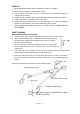
6 Keep mounting surface of brackets as close to being flush with the front of the bumper as possible to allow free vertical travel. 7 Attach tow bar to properly mounted brackets with pins and secure with attached wire. 8 Adjust coupler for proper fit to the ball; See COUPLER ADJUSTMENT in the Chapter of INSTALLATION. TOWED VEHICLE ATTACHMENT A structure must be fabricated to allow the tow bar to be attached to the frame of the towed vehicle.
Warning label 1: READ WARNINGS CAREFULLY. 1. Use only a 2” ball rated for at least 5000 pounds. 2. Properly connect safety chains from tow bar to towing vehicle and towed vehicle. 3. Read and follow label on side of tow bar, coupler and instruction before towing. Warning label 2: WARNING! FAILURE TO FOLLOW THESE INSTRUCTIONS MAY RESULT IN A HAZARDOUS TOWING CONDITION. DO NOT REMOVE THIS LABEL. 1. Total weight of towed vehicle must not exceed 5,000 pounds. 2.
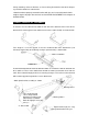
HOOK UP 1. Attach tow bar to tow bar brackets with two wire lock pins as part#10. 2. Attach tow bar coupler to 2” ball of towing vehicle. 3. Center coupler on tow bar side arms so that tow bar is symmetrical about the centerline of the vehicles. 4. Tighten the 3/8” nuts which attach the tow bar side arms to the coupler to 31 LB-FT. 5. Install safety chains as described in the next section. 6.
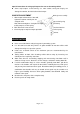
Special instructions for using a pickup truck or van as the towing vehicle Some step bumpers restrict turning, use extra caution, tuning too sharply can damage the tow bar, the hitch ball and the bumper. COUPLER ADJUSTMENT locking lever assembly 1. With coupler locked onto a 2” dia. Ball, tighten the locknut until all parts are clamped solid. Note: Do not overtighten. Just tighten enough to fully compress helical spring. 2. Back locknut off 1/2 to 3/4 turn. 3.
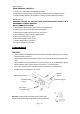
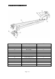
PARTS DRAWING & DIAGRAM Part# Description QTY 1 Coupler(For Use W/2" Hitch Ball) 1 2 Side arm 2 3 Bolt assembly 2 4 Washer-Conical Toothed 3/8 4 5 Locknut-Hex 3/8-16 4 6 Pivot bracket assembly 2 7 Bolt-Hex 1/2 -13x3.50 2 8 Locknut- Flange 1/2-13 2 9 Tow bar bracket 2 10 Wire lock pin 2 11 Flat Washer 4 12 Hex bolt 1/2 -13x3.
WARRANTY One-year limited warranty. For warranty questions, call 1-800-222-5381. Distributed by Northern Tool + Equipment Co., Inc. Burnsville, MN 55306 NorthernTool.