
Specifications


Table Of Contents
- iXon Ultra
- SAFETY AND WARNINGS INFORMATION
- SAFETY AND WARNINGS SYMBOLS
- MANUAL HANDLING
- SHIPPING AND STORAGE PRECAUTIONS
- SECTION 1 - INTRODUCTION TO IXON ULTRA HARDWARE
- 1.1 - TECHNICAL SUPPORT
- 1.2 - DISCLAIMER
- 1.3 - TRADEMARKS AND PATENT INFORMATION
- 1.4 - COMPONENTS
- 1.4.1 - Camera description
- 1.4.2 - Camera Power Supply Unit
- 1.4.3 - SOFTWARE
- 1.5 - SPECIFICATIONS
- 1.6 - ACCESSORIES
- 1.7 - SAFETY PRECAUTIONS AND MAINTENANCE
- 1.7.1 - Care of the camera
- 1.7.2 - Regular checks
- 1.7.3 - Annual electrical safety checks
- 1.7.4 - Replacement parts
- 1.7.5 - Fuse replacement
- 1.7.6 - Working with electronics
- 1.7.7 - Condensation
- 1.7.8 - Dew Point graph
- 1.7.9 - EM Gain ageing
- 1.7.10 - Minimizing particulate contamination
- 2.1 - INSTALLING THE HARDWARE
- 2.1.1- PC requirements
- 2.2 - INSTALLING ANDOR SOLIS SOFTWARE - WINDOWS O/S(XP/VISTA/SEVEN)
- 2.3 - NEW HARDWARE WIZARD
- 2.5 - WATER PIPE CONNECTORS
- 2.6 - MOUNTING POSTS
- 2.7 - COOLING
- 2.8 - START-UP DIALOG
- 3.1 - EMCCD OPERATION
- 3.1.1 - Structure of an EMCCD
- 3.1.2 - EM Gain & Read Noise
- 3.1.3 - EM Gain ON vs EM Gain OFF
- 3.1.4 - Multiplicative Noise Factor and Photon Counting
- 3.1.5 - EM Gain dependence and stability
- 3.1.6 - RealGain: Real and Linear gain
- 3.1.7 - EM Gain Ageing: What causes it and how is it countered?
- 3.1.8 - Gain and signal restrictions
- 3.1.9 - EMCAL
- 3.2 - COOLING
- 3.2.1 - Cooling options
- 3.2.2 - Heat generated in the EMCCD
- 3.2.3 Heatsink “hot side“ temperature
- 3.2.4 - Fan settings
- 3.3 - SENSOR READOUT OPTIMIZATION
- 3.3.1 - Sensor Pre-amp options
- 3.3.2 - Variable Horizontal Readout Rate
- 3.3.3 - Variable Vertical Shift Speed
- 3.3.4 - Output amplifier selection
- 3.3.5 - Baseline Optimization
- 3.3.5.1 - Baseline Clamp
- 3.3.6 - Binning and Sub Image options
- 3.4 - ACQUISITION OPTIONS
- 3.4.1 - Capture Sequence in Frame Transfer (FT) Mode
- 3.4.1.1 - Points to consider when using FT Mode
- 3.4.2 - Capture Sequence in Non-Frame Transfer Mode (NFT) with an FT EMCCD
- 3.4.2.1 - Points to note about using an FT EMCCD as a standard EMCCD
- 3.4.3 - Capture Sequence for Fast Kinetics (FK) with an FT EMCCD
- 3.4.3.1 - Points to consider when using Fast Kinetics mode
- 3.4.4 - Keep Clean Cycles
- 3.5 - TRIGGERING OPTIONS
- 3.5.1 - Triggering options in Frame Transfer (FT) mode
- 3.5.1.1 - Internal Triggering (FT)
- 3.5.1.2 - External Triggering (FT)
- 3.5.1.3 - External Exposure (FT)
- 3.5.2 - Triggering options in Non-Frame Transfer (NFT) mode
- 3.5.2.1 - Internal (NFT)
- 3.5.2.2 - External & Fast External (NFT)
- 3.5.2.3 - External Exposure (NFT)
- 3.5.2.4 - Software trigger (NFT)
- 3.5.3 - Trigger options in Fast Kinetics (FK) mode
- 3.5.3.1 - Internal (FK)
- 3.5.3.2 - External (FK)
- 3.5.3.3 - External Start (FK)
- 3.6 - SHUTTERING
- 3.7 - COUNT CONVERT
- 3.8 - OPTACQUIRE
- 3.8.1 - OptAcquire modes
- 3.9 - PUSHING FRAME RATES WITH CROPPED SENSOR MODE
- 3.9.1 - Cropped Sensor Mode Frame Rates
- 3.10 - ADVANCED PHOTON COUNTING IN EMCCDs
- 3.10.1 - Photon Counting by Post-Process
- 3.11 - SPURIOUS NOISE FILTER
- 4.1 - EMCCD TECHNOLOGY
- 4.1.1 - What is an Electron Multiplying CCD?
- 4.1.2 - Does EMCCD technology eliminate Read Out Noise?
- 4.1.3 - How sensitive are EMCCDs?
- 4.1.4 - What applications are EMCCDs suitable for?
- 4.1.5 - What is Andor Technology's experience with EMCCDs?
- 4.2 - EMCCD SENSOR
- 4.3 - VACUUM HOUSING
- 4.3.1 - Thermoelectric cooler
- 4.4 – USB 2.0 INTERFACE
- 4.5 - OUTGASSING
- 4.6 - EXTERNAL I/O
- 4.7 - SIGNAL DIAGRAMS
- 4.8 - CAMERALINK
- SECTION 5: TROUBLESHOOTING
- 5.1 - UNIT DOES NOT SWITCH ON
- 5.2 - SUPPORT DEVICE NOT RECOGNISED WHEN PLUGGED INTO PC
- 5.3 - TEMPERATURE TRIP ALARM SOUNDS (CONTINUOUS TONE)
- 5.4 - CAMERA HIGH FIFO FILL ALARM
- 5.5 - USE OF MULTIPLE HIGH SPEED USB 2.0 I/O ON ONE CAMERA
- A.1 - GLOSSARY
- A.1.1 - Readout sequence of an EMCCD
- A.1.2 - Accumulation
- A.1.3 - Acquisition
- A.1.4 - A/D Conversion
- A.1.5 - Background
- A.1.6 - Binning
- A.1.7 - Counts
- A.1.8 - Dark Signal
- A.1.9 - Detection Limit
- A.1.10 - Exposure Time
- A.1.11 - Frame Transfer
- A.1.12 - NOISE
- A.1.12.1 - Pixel Noise
- A.1.12.1.1 - Readout Noise
- A.1.12.1.2 - Shot Noise
- A.1.12.1.2.A - Shot Noise from the Signal
- A.1.12.1.2.B - Shot Noise from the Dark Signal
- A.1.12.1.3 - Calculation of Total Pixel Noise
- A.1.12.2 - Fixed Pattern Noise
- A.1.13 - Quantum Efficiency/Spectral Response
- A.1.14 - Readout
- A.1.15 - Saturation
- A.1.16 - Scans (Keep Clean and Acquired)
- A.1.17 - Shift Register
- A.1.18 - Signal To Noise Ratio
- B - MECHANICAL DIMENSIONS
- C - DECLARATION OF CONFORMITY
- D - HARDWARE AND SOFTWARE WARRANTY SERVICE
- D.1 - SERVICE DESCRIPTION
- D.2 - Access to Service
- D.3 - Hardware Remediation
- D.4 - Software Remediation
- E - THE WASTE ELECTRONIC AND ELECTRICAL EQUIPMENT REGULATIONS 2006 (WEEE)
Version 1.1 rev Jan 2013
Page 53
iXon Ultra
, Features and Functionality
3.3.4 - Output amplier selection
The iXon Ultra camera incorporates dual output ampliers, an electron multiplying output amplier and a conventional
output amplier. This increases the versatility of the camera as the EM amplier can be selected for fast imaging in low-
light conditions, whilst the conventional amplier can be selected where more light is available and a slower readout,
with its associated lower read noise and higher dynamic range, is preferred.
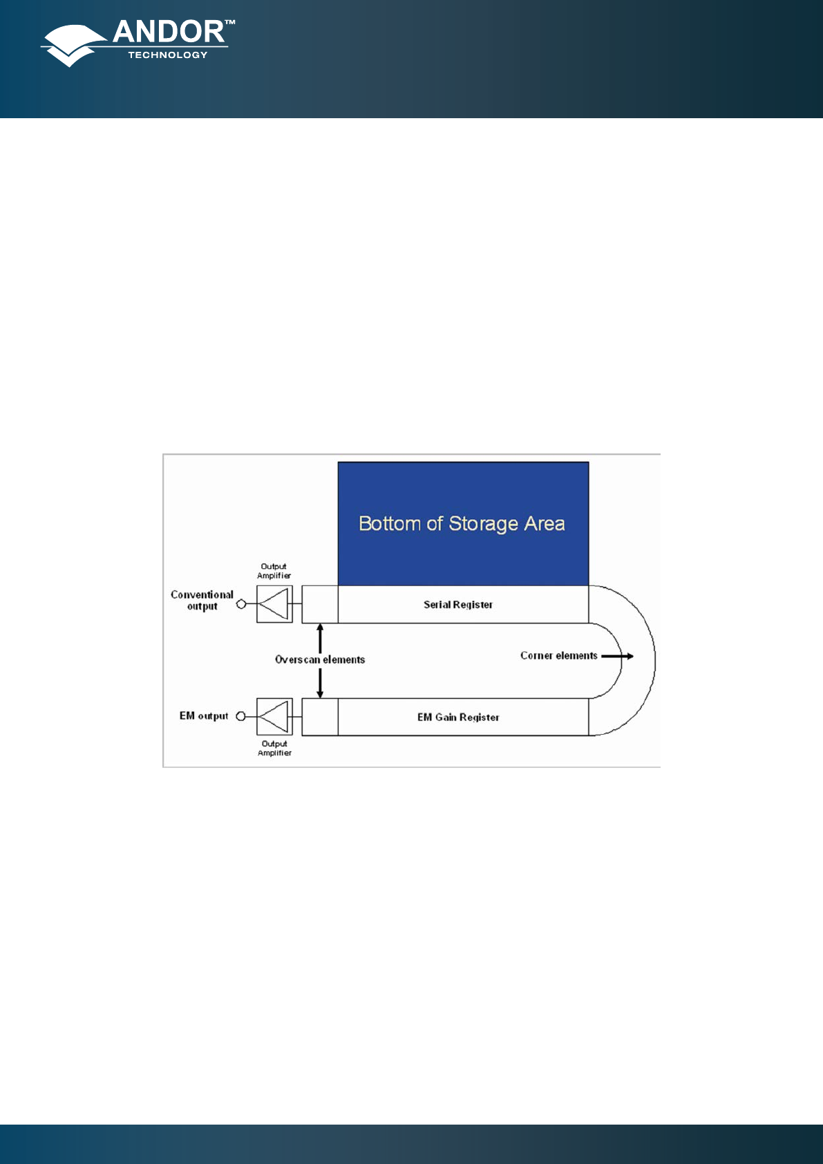
The readout structure on sensors with both output ampliers present is shown in Figure 16. From this it can be seen
that, when reading out through the EM amplier, accumulated charge will move to the right along the serial register
and then into the EM Gain register. When the conventional output amplier is selected, the charge to be read out will
move along the serial register to the left then be transferred directly into the conventional output amplier. This change
in direction has the effect of producing mirror images when comparing raw data from the two output ampliers. Some
software packages will automatically reverse the image orientation of one of the output ampliers to allow direct
comparison of images. Consult your software manual to verify if this is the case.
Figure 16: Sensor readout structure