
Specifications


Table Of Contents
- iXon Ultra
- SAFETY AND WARNINGS INFORMATION
- SAFETY AND WARNINGS SYMBOLS
- MANUAL HANDLING
- SHIPPING AND STORAGE PRECAUTIONS
- SECTION 1 - INTRODUCTION TO IXON ULTRA HARDWARE
- 1.1 - TECHNICAL SUPPORT
- 1.2 - DISCLAIMER
- 1.3 - TRADEMARKS AND PATENT INFORMATION
- 1.4 - COMPONENTS
- 1.4.1 - Camera description
- 1.4.2 - Camera Power Supply Unit
- 1.4.3 - SOFTWARE
- 1.5 - SPECIFICATIONS
- 1.6 - ACCESSORIES
- 1.7 - SAFETY PRECAUTIONS AND MAINTENANCE
- 1.7.1 - Care of the camera
- 1.7.2 - Regular checks
- 1.7.3 - Annual electrical safety checks
- 1.7.4 - Replacement parts
- 1.7.5 - Fuse replacement
- 1.7.6 - Working with electronics
- 1.7.7 - Condensation
- 1.7.8 - Dew Point graph
- 1.7.9 - EM Gain ageing
- 1.7.10 - Minimizing particulate contamination
- 2.1 - INSTALLING THE HARDWARE
- 2.1.1- PC requirements
- 2.2 - INSTALLING ANDOR SOLIS SOFTWARE - WINDOWS O/S(XP/VISTA/SEVEN)
- 2.3 - NEW HARDWARE WIZARD
- 2.5 - WATER PIPE CONNECTORS
- 2.6 - MOUNTING POSTS
- 2.7 - COOLING
- 2.8 - START-UP DIALOG
- 3.1 - EMCCD OPERATION
- 3.1.1 - Structure of an EMCCD
- 3.1.2 - EM Gain & Read Noise
- 3.1.3 - EM Gain ON vs EM Gain OFF
- 3.1.4 - Multiplicative Noise Factor and Photon Counting
- 3.1.5 - EM Gain dependence and stability
- 3.1.6 - RealGain: Real and Linear gain
- 3.1.7 - EM Gain Ageing: What causes it and how is it countered?
- 3.1.8 - Gain and signal restrictions
- 3.1.9 - EMCAL
- 3.2 - COOLING
- 3.2.1 - Cooling options
- 3.2.2 - Heat generated in the EMCCD
- 3.2.3 Heatsink “hot side“ temperature
- 3.2.4 - Fan settings
- 3.3 - SENSOR READOUT OPTIMIZATION
- 3.3.1 - Sensor Pre-amp options
- 3.3.2 - Variable Horizontal Readout Rate
- 3.3.3 - Variable Vertical Shift Speed
- 3.3.4 - Output amplifier selection
- 3.3.5 - Baseline Optimization
- 3.3.5.1 - Baseline Clamp
- 3.3.6 - Binning and Sub Image options
- 3.4 - ACQUISITION OPTIONS
- 3.4.1 - Capture Sequence in Frame Transfer (FT) Mode
- 3.4.1.1 - Points to consider when using FT Mode
- 3.4.2 - Capture Sequence in Non-Frame Transfer Mode (NFT) with an FT EMCCD
- 3.4.2.1 - Points to note about using an FT EMCCD as a standard EMCCD
- 3.4.3 - Capture Sequence for Fast Kinetics (FK) with an FT EMCCD
- 3.4.3.1 - Points to consider when using Fast Kinetics mode
- 3.4.4 - Keep Clean Cycles
- 3.5 - TRIGGERING OPTIONS
- 3.5.1 - Triggering options in Frame Transfer (FT) mode
- 3.5.1.1 - Internal Triggering (FT)
- 3.5.1.2 - External Triggering (FT)
- 3.5.1.3 - External Exposure (FT)
- 3.5.2 - Triggering options in Non-Frame Transfer (NFT) mode
- 3.5.2.1 - Internal (NFT)
- 3.5.2.2 - External & Fast External (NFT)
- 3.5.2.3 - External Exposure (NFT)
- 3.5.2.4 - Software trigger (NFT)
- 3.5.3 - Trigger options in Fast Kinetics (FK) mode
- 3.5.3.1 - Internal (FK)
- 3.5.3.2 - External (FK)
- 3.5.3.3 - External Start (FK)
- 3.6 - SHUTTERING
- 3.7 - COUNT CONVERT
- 3.8 - OPTACQUIRE
- 3.8.1 - OptAcquire modes
- 3.9 - PUSHING FRAME RATES WITH CROPPED SENSOR MODE
- 3.9.1 - Cropped Sensor Mode Frame Rates
- 3.10 - ADVANCED PHOTON COUNTING IN EMCCDs
- 3.10.1 - Photon Counting by Post-Process
- 3.11 - SPURIOUS NOISE FILTER
- 4.1 - EMCCD TECHNOLOGY
- 4.1.1 - What is an Electron Multiplying CCD?
- 4.1.2 - Does EMCCD technology eliminate Read Out Noise?
- 4.1.3 - How sensitive are EMCCDs?
- 4.1.4 - What applications are EMCCDs suitable for?
- 4.1.5 - What is Andor Technology's experience with EMCCDs?
- 4.2 - EMCCD SENSOR
- 4.3 - VACUUM HOUSING
- 4.3.1 - Thermoelectric cooler
- 4.4 – USB 2.0 INTERFACE
- 4.5 - OUTGASSING
- 4.6 - EXTERNAL I/O
- 4.7 - SIGNAL DIAGRAMS
- 4.8 - CAMERALINK
- SECTION 5: TROUBLESHOOTING
- 5.1 - UNIT DOES NOT SWITCH ON
- 5.2 - SUPPORT DEVICE NOT RECOGNISED WHEN PLUGGED INTO PC
- 5.3 - TEMPERATURE TRIP ALARM SOUNDS (CONTINUOUS TONE)
- 5.4 - CAMERA HIGH FIFO FILL ALARM
- 5.5 - USE OF MULTIPLE HIGH SPEED USB 2.0 I/O ON ONE CAMERA
- A.1 - GLOSSARY
- A.1.1 - Readout sequence of an EMCCD
- A.1.2 - Accumulation
- A.1.3 - Acquisition
- A.1.4 - A/D Conversion
- A.1.5 - Background
- A.1.6 - Binning
- A.1.7 - Counts
- A.1.8 - Dark Signal
- A.1.9 - Detection Limit
- A.1.10 - Exposure Time
- A.1.11 - Frame Transfer
- A.1.12 - NOISE
- A.1.12.1 - Pixel Noise
- A.1.12.1.1 - Readout Noise
- A.1.12.1.2 - Shot Noise
- A.1.12.1.2.A - Shot Noise from the Signal
- A.1.12.1.2.B - Shot Noise from the Dark Signal
- A.1.12.1.3 - Calculation of Total Pixel Noise
- A.1.12.2 - Fixed Pattern Noise
- A.1.13 - Quantum Efficiency/Spectral Response
- A.1.14 - Readout
- A.1.15 - Saturation
- A.1.16 - Scans (Keep Clean and Acquired)
- A.1.17 - Shift Register
- A.1.18 - Signal To Noise Ratio
- B - MECHANICAL DIMENSIONS
- C - DECLARATION OF CONFORMITY
- D - HARDWARE AND SOFTWARE WARRANTY SERVICE
- D.1 - SERVICE DESCRIPTION
- D.2 - Access to Service
- D.3 - Hardware Remediation
- D.4 - Software Remediation
- E - THE WASTE ELECTRONIC AND ELECTRICAL EQUIPMENT REGULATIONS 2006 (WEEE)
Version 1.1 rev Jan 2013
Page 18
iXon Ultra
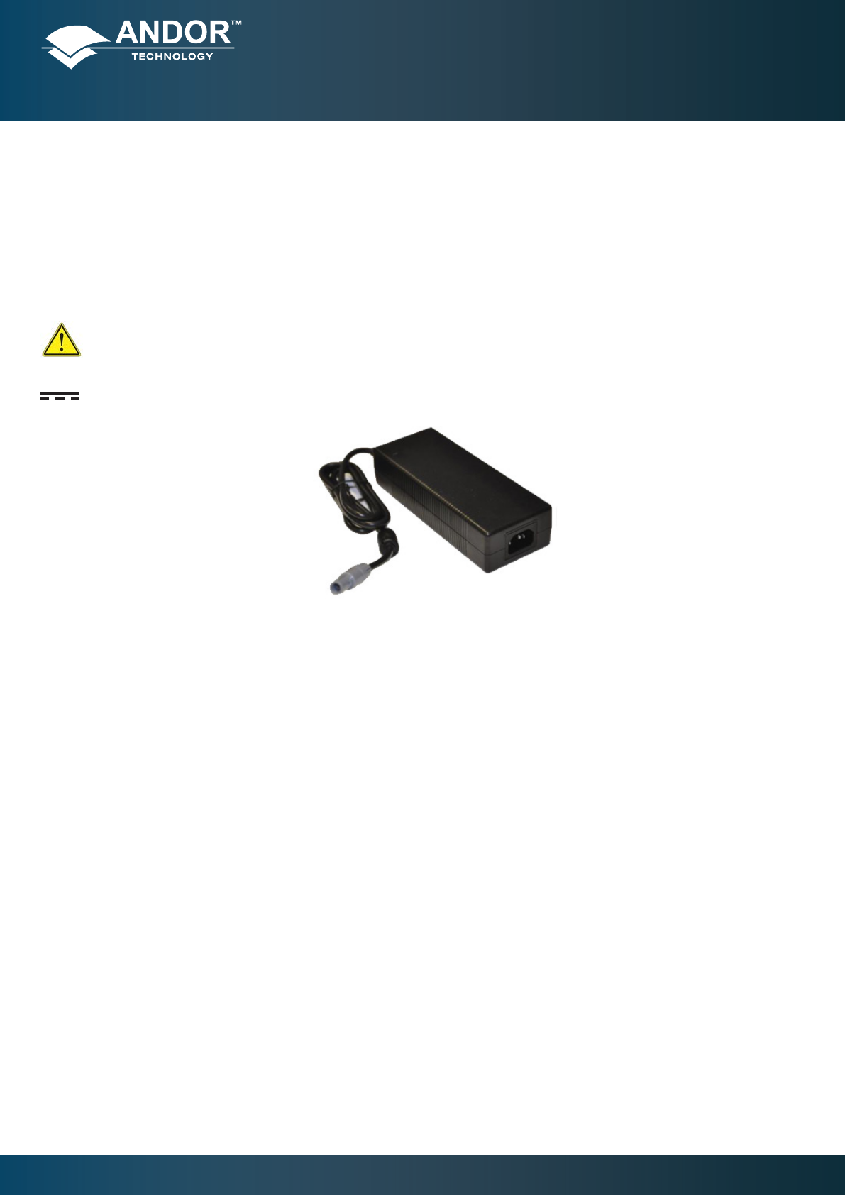
1.4.2 - Camera Power Supply Unit
The iXon Ultra system is designed to be powered from an SW4189 external PSU (Andor P/N PS-90) as shown in Figure
2. This requires an AC mains input between 100-240 V, 47-63 Hz and a maximum supply current of 1.6 A.
The output of the SW4189 is 12 V DC at 9 A maximum. However the maximum camera power consumption is 12 V at
6 A = 72 Watts. The SW4189 PSU is tted with an IEC connector for the electrical supply input. The connection to the
iXonUltraismadeviaa3pinRedelcableplug(PartNo.PAH.N0.3GL.LC65GZ).
The SW4189 is for use with Telecommunications, Computer, Industrial Controller and OA Systems and must only
be used indoors.
The iXon Ultra camera head requires a Direct Current (DC) supply.
Figure 2: PS-90 PSU
WARNING: The electrical mains lead should be certied for use in your country and in applicable countries the
plug must be tted with a 240V 5A fuse. If users use any other power supply, they do so at their own risk.
1.4.3 - SOFTWARE
Your iXon Ultra may have been supplied with Andor Solis or Andor iQ software, or with the Andor SDK. However it
is also compatible with a range of third party software options offering optimized acquisition control and analysis
functionality. For further details of Andor software capabilities and software options, please go to the following page on
our website: http://www.andor.com/products/software/
Introduction to iXon Ultra Hardware