
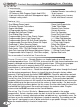
Installation guide


Installation Guide
Installation Guide
1600 Wiring Diagram Page 3
Pre-Installation Page 4
What’s Included
Pre Installation Check
Installation Procedures
Wire Connectors Page 5
6 Pin Connector
14 Pin Connector
4 Pin Red Connector
Jumper Settings
Installation Page 6-7
Basic Installation - Quick start
Under Hood Connections
Installing The Antenna
Mounting The Module
Operating The System
Programming Page 7-9
Program Overview & System Reset
Program Menu 1 (User Settings)
Program Menu 3 (Starter Settings)
Program Menu 4 (Tach Settings)
Operations Page 10
Single & Dual Car Operation
Timer Mode
Manual Transmission (Reservation Mode)
Additional Operations Page 11
1st & Second Car Transmitter Programming
Battery Replacement
Emergency System Service Mode
Relay Diagrams Page 12
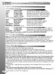
WIRING DIAGRAM
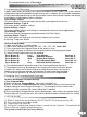
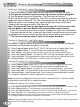
If the remote starter has a failed start attempt or if a safety input is activated the Diagnostic Memory will
store up to four shutdowns in memory. This information can then be accessed to determine the source
of the shutdown.
To Enter Diagnostic Mode:
Step 1 - Turn the ignition on wait two seconds then turn off. Press the Program Button and release.
Step 2 - The system will respond with three park light flashes and the horn will honk (optional) the
same number of times as the events in memory. ( Maximum four events, four honks)
NOTE: If the horn does not honk, there are no events in memory.
Step 3 - Press the Program Button once to view the last shut down code. The (optional) Horn will
honk once to confirm code one. (If the horn does not honk, there are no codes in memory).
Step 4 - The LED’s on the antenna will flash a code corresponding to a shut down trigger. Press the
Program Button again to check the second code. The horn will honk twice to confirm code two.
Step 5 - To Clear Diagnostic Memory. While in Diagnostic Mode press and hold the Program Button
for five seconds. The park lights will flash and the horn(optional) will honk once.
NOTE: Once diagnostic memory has 4 shutdown events in memory, the system will not record any
Further shutdown events until the system memory has been cleared.
DIAGNOSTICS
2
3
RED
GREEN
BLUE
PINK
Green
Yellow
Red
Red
(-) Park Light/Output 5*
Horn Honk Output
YELLOW
BLACK
Door Lock Output
Low Current 12 volt Output***
Door Unlock Output
Second Unlock Output
11
33
55
22
44
66
22
11
44
33
66
55
77
88
1010
99
1212
1111
1414
1313
Re-Arm/Output 1*
Starer Disable/Output 4*
Disarm/Output 2*
Trunk Release/Output 3*
Negative When Running
Negative door pin input**
Hood pin switch input
Positive door pin input**
Brake switch Input
Ground Input
Tach Input
Glow Plug Input
Positive Park Light
Park Brake Input**
4 PIN
BLUE
4
PI
N
R
ED
P
N
2 I
W
H
I
T
E
RF ANTENNA WITH DUAL LED’S AND
BUILT-IN VALET SWITCH
(+) 30amp Output
(+) 30amp Output
(+) 30amp Input
(+) 30amp Input
(+) 30amp Output
(+) 30amp Output
(-)500ma Output
(-)500ma Output
(-)500ma Output
(-)500ma Output
(-)500ma Output
(-)500ma Output
(-)500ma Output
(-)500ma Output
(-)500ma Output
(-)500ma Output
(+)500ma Output
Negative Input
Negative Input
Negative Input
Negative Input
(A/C) Input
(+/-) Input
Positive Input
Positive 15amp
Positive Input
EXTRA LED OUTPUT (OPTIONAL)
Must be disconnected until all programming is complete
TEMPERATURE SENSOR INPUT (OPTIONAL)
The antenna must be connected for the system to operate.
White
Blue
Starter Output
Accessory Output
Main Power
Main Power
Selectable Output
Ignition 1 Output
Yellow
Orange
Brown
Red / White
White / Violet
Green
Green / White
Purple
Pink
Black
Blue / White
Blue
White
Black / White
Jumper Access
See Page 5
* These Outputs are programable. See page 11 For programming details.
** These wires are only needed for Manual Transmission applications.
*** This wire is to only be used as a low current output.
Table Of Contents
PARK LIGHTS STATUS LED DIAGNOSTIC CODE
3 Flashes Series of 3 Flashes Door Opened “M” Models
3 Slow Flashes LED’s On Solid System Is In Service Mode
4 Slow Flashes Series of 4 Flashes Not in Reservation Mode “M” units
5 Flashes Series of 5 Flashes Hood Pin Opened
5 Slow Flashes Series of 5 Flashes Ignition On During Start Attempt
6 Flashes Series of 6 Flashes Brake Pedal Shutdown
7 Flashes Series of 7 Flashes Tach Lock-Out
8 Flashes Series of 8 Flashes 3 Start Attempts With No Start