INSTALL GUIDE 600 Series Remote Vehicle Security System WWW.ULTRASTARTERS.COM Technical Support- 866.698.5872 FCC/ID Notice This device complies with Part 15 of the FCC rules. Operation is subject to the following conditions: (1) This device may not cause harmful interference, and (2) This device must accept any interference received, including interference that may cause undesired operation.
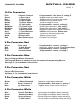
INSTALL GUIDE SECURITY SYSTEM PAGE 2 Table of Contents Table of Contents Components Page 2 600 Wiring Diagram Page 3 Installation Tips Pre-Installation Suggestions Page 4 Installation Suggestions Mounting The Module Installing The LED Installing The Program Button Connecting The Starter Disable Connecting The Dome Light Supervision Under Hood Connections Mounting The Siren Page 4 Wire Connectors 14 Pin Main Harness Connector 4 Pin Red Connector- Keyless Entry 2 Pin Connector Red- Plug-in LED 2 Pi
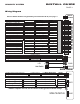
INSTALL GUIDE SECURITY SYSTEM PAGE 3 Wiring Diagram Starter Disable Built-in Starter Disable relay (Normally Connected 87a & 30). See page. 5 500ma Output Channel 4 Pink Connect to (-) door pin (-) Input (-) Door Input Green Connect to hood pin (-) Input Hood Input Blue Connect to (+) door pin (+) Input (+) Door Input Purple Connect to Siren 3amp Output (+) Siren Brown Connect to park lights 15amp Output (+) Park Lights White See page. 4 (+.
INSTALL GUIDE SECURITY SYSTEM PAGE 4 Recommended Pre-Installation Procedures BEFORE STARTING INSTALLATION: - Discuss the optional system features with the customer. - Take a few minutes to review the installation and owners manuals. - Do a walk around the vehicle and check for any damage. - If installing a LED discuss the placement with customer before installing. Recommended Installation Procedures Mounting the Module Never mount the module in the engine compartment.
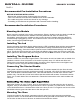
INSTALL GUIDE SECURITY SYSTEM PAGE 5 14 Pin Connector Pink Green Blue Purple Brown White Blk/White Blk/White Orange Grey Yellow Black Red Channel 4 Output (-) Door Input (-) Hood Input (+) Door Input (+) Siren Output (+) Park lights (+/-) Dome Light (+/-) Dome Light (-) When Armed (-) Trunk Release Ignition Input Ground Input Main Power Input Programmable - See menu 2, setting 5. Negative door pin switch input. Negative input from hood pin switch. Positive door pin switch input.
INSTALL GUIDE SECURITY SYSTEM PAGE 6 Quick Start Install Step 1 - Connect All Of the Following Wires 14 Pin Power Connector Black Yellow Red White Green* Purple* Ground Input Ignition Input MainPower Input (+) Park lights (-) Door Input (+) Door Input System ground input. Input from vehicles ignition wire. Positive output for siren. Programmable - menu 2, setting 3. Negative door pin switch input. Positive door pin switch input.
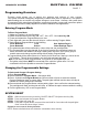
SECURITY SYSTEM INSTALL GUIDE PAGE 7 Programming Overview Program mode allows you to adjust the settings and options of your system. Your system has been intelligently designed by installers with years of experience. The system’s default settings do not require any program changes in most cases. However, this system does incorporate a highly advanced programming system that includes 2 menus with numerous options and settings that can be easily adjusted for custom installations and applications.
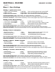
INSTALL GUIDE SECURITY SYSTEM PAGE 8 Menu 1 - User Settings Setting 1- Ignition Auto Lock 1 Ignition Lock & Unlock Enabled 1 Light Flash Doors Lock/Unlock when the key is turned On/Off 2 Ignition Lock Only 2 Light Flashes Doors Lock when ignition key is turned ON only *3 Ignition Auto Lock Disabled 3 Light Flashes Doors do not Lock or Unlock with Ignition key Press the Valet Switch 1 time to select setting 1 (This will be confirmed by 1 LED flashes) Press and hold the Valet Switch until you receive the a
INSTALL GUIDE SECURITY SYSTEM PAGE 9 Menu 2- Alarm Settings Setting 1 - Car Finder/ 5th Channel 1 Car Finder OFF 1 Light Flash Car Finder Mode Disabled *2 Car Finder ON 2 Light Flashes Car Finder Mode Enabled **To operate the 5th channel on button #4, setting 7 must be programmed for 5th channel output. Press the Valet Switch 1 time to select setting 1 (This will be confirmed by 1 LED flashes) Press and hold the Valet Switch until you receive the appropriate # of park light flashes and/or siren chirps.
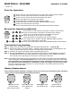
INSTALL GUIDE SECURITY SYSTEM PAGE 10 First Car Operation Press Once to Lock the doors and arm the alarm. Hold for Panic Mode. Press a second time and hold for Constant Lock Output. First Car Press once to unlock the doors and disarm the alarm Press and hold for the Trunk / Aux Output Press this button to activate the 4th channel output. This output can be used to activate additional alarm features. Press once and hold for Car Finder Press and release then hold to activate/deactivate Service Mode.
SECURITY SYSTEM INSTALL GUIDE PAGE 11 System Service Mode ACTIVATING SERVICE MODE 1. While the ignition is “ON” press and hold the Program Button for five seconds. The park lights will flash and the siren will chirp five times to confirm that the system is in Service Mode. 2. While in Service Mode the remote start functions will be disabled and LEDs will be “ON” steady. Door locks and trunk release are still operational. DEACTIVATING SERVICE MODE 1.
INSTALL GUIDE SECURITY SYSTEM PAGE 12 Diagnostics Alarm Diagnostics If the alarm system is triggered while armed, the system will retain in memory the cause of the trigger. The diagnostics can then be used to determine what the cause of the trigger was. When disarming the alarm, the siren/horn will chirp 3 times instead of the usual 2 times to indicate the alarm had been triggered. The system’s LED will also flash in pulses to indicate which input triggered the alarm.