
Install guide


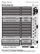


ACTIVE RF ANTENNA**
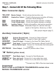
NOTE: The jumpers control the output from the WHITE wire on the
main 6- pin harness. This is an 30amp relayed output.
*The factory default setting of the Selectable Output jumper is position #3.
Output on White wire Jumper position
Second Starter Position 1
Second Accessory Position 2
Second Ignition Position 3
Status Leds
Program Button
**The antenna MUST be connected for the system to operate
*The centre pin of the keyless entry harness is ONLY available with
plug-in devices such as the VP-1, DL-3, DL-7 and Data Bus Modules.
Overloading this output will damage the remote starter.
Wiring Diagram
REMOTE VEHICLE STARTER INSTALL MANUAL
PAGE 7
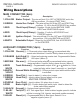
GREEN
BLUE
GREEN
RED*
GREEN
PINK
BLUE
BLACK
BLUE
PINK
RED
Door Lock Output (-)250ma
Pre-Warn Sensor Input (-)
Horn/ Aux #5 Output (-)250ma
12v Output (+)250ma (see notes below)*
Full-Warn Sensor Input
Aux #6 Output
Door Unlock Output (-)250ma
Ground Output (-)250ma
12Volt Disconnect/ Start Input (+)
2nd Door Unlock Output (-)250ma
12Volt Output (+)250ma
1
2
3
4
1
2
3
1
2
3
4
1
2
(-) Input Trigger
Temperature Sensor (LT Series Only)
continued...
NOTE: 250ma outputs are low current and may require
additional parts (relays) to active optional features.
N/A
3 2 1