FCC/ID Notice This device complies with Part 15 of the FCC rules. Operation is subject to the following conditions: (1) This device may not cause harmful interference, and (2) This device must accept any interference received, including interference that may cause undesired operation. CAUTION: Changes or modifications not expressly approved by the part responsible for compliance void the user’s authority to operate this devise.
INSTALLATION GUIDE TABLE OF CONTENTS 2250 Wiring Diagram Pre-Installation Components Recommended Pre-Installation Procedures Recommended Install Procedures Wire Connectors 6 Pin Connector 14 Pin Connector 3 Pin Red Connector 4 Pin Blue Connector Jumper Selections Installation Basic Installation - Quick start Plugging In The Module Auto Tach Learn Shock Sensor Programming Programming Program Overview & System Reset Program Menu 1 (User Settings) Program Menu 2 (Alarm Settings) Program Menu 3 (Starter Settin
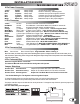
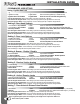
INSTALLATION GUIDE WIRING DIAGRAM YELLOW RED/WHITE BROWN ORANGE WHITE/BLUE BLACK/WHITE PURPLE WHITE GREEN/WHITE GREEN BLACK PINK BLUE/WHITE BLUE *This input is a optional connection for “TL” models. This input is programmable and may need to be programmed for Tachless operation. See Page 11. SIDE VIEW Note: The center pin of this connector is low current and designed to power a Voltage Inverter. Do not use the center pin of this connector to power relay packs. Doing so will damage the output.
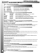
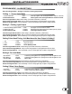
INSTALLATION GUIDE INSTALLATION TIPS Components - Control module - Remote transmitter(s) - Antenna with built in program button and LED’s - 6 pin main harness with dual 30amp power inputs - 14 pin harness - 3 pin - 2 wire keyless entry harness - Multi-tone siren - Hood pin safety switch - Hood and window stickers - Installation guide - Owners manual Recommended Pre-Installation Procedures BEFORE STARTING INSTALLATION: - Discuss the optional features with the customer.
INSTALLATION GUIDE WIRING CONNECTIONS 6 Pin Power Connector Yellow Green Red Red Blue White Starter Heater 12 power 12 power Ignition 1 Select Out 30amp output 30amp output 30amp input 30amp input 30amp output 30amp output 12volts during crank only. 12volts in accessory. Off during start. Constant 12volt power at ignition harness. Constant 12volt power at ignition harness. 12volts in ignition and start positions. Selectable Output. See jumper diagram.
INSTALLATION GUIDE QUICK START INSTALL Step 1 - Connect All Of the Following Wires 6 Pin Power Connector Yellow Green Red Red Blue White Starter Output Heater Output 12 power Input 12 power Input Ignition 1 Output Selectable Output Connect The Yellow Wire From The 6 Pin To The Vehicles Starter Wire. Connect The Green Wire From The 6 Pin To The VehiclesAccessory Wire. Connect to Constant 12 Volt Power Source- High Current. Connect to Constant 12 Volt Power Source- High Current.
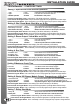
INSTALLATION GUIDE PROGRAMMING Programming Overview Program mode allows you to adjust the settings and options of your system. Your system has been intelligently designed by installers with years of experience. The system’s default settings do not require any program changes in most cases. However, this system does incorporate a highly advanced programming system that includes 4 menus with numerous options and settings that can be easily adjusted for custom installations and applications.
INSTALLATION GUIDE PROGRAMMING PROGRAM MODE - USER SETTINGS Setting 1- Ignition Auto Lock 1 Ignition Lock & Unlock Enabled 2 Ignition Lock Only *3 Ignition Auto Lock Disabled 1 Light Flash 2 Light Flashes 3 Light Flashes Doors Lock / Unlock when the key is turned On/ Off Doors Lock when ignition key is turned ON only Doors do not Lock or Unlock with Ignition key Press the Program Button 1 time to select setting 1 (This will be confirmed by 1 LED flash) Press and hold the Program Button until you receive
INSTALLATION GUIDE PROGRAMMING PROGRAM MODE - ALARM SETTINGS Enter Alarm Program Mode - See Page 7 for details on entering program mode Setting 1 - Secure Valet Mode 1 Secure Valet Active 2* Normal Valet Active 1 Flash 2 Flashes Valet only if ignition “ON” and Program Button is held for 15 seconds Valet if ignition “ON” and Program Button is held for 5 seconds Press the Program Button 1 time to select setting 1 (This will be confirmed by 1 LED flash) Press and hold the Program Button until you receive t
INSTALLATION GUIDE PROGRAMMING PROGRAM MODE - STARTER SETTINGS Setting 1- Special Door Lock/ Unlock Operations 1 Type 1 2 Type 2 3* Normal Operation 1 Flash 2 Flashes 3 Flashes Unlock before start and a lock pulse after start & shutdown Lock pulse after remote starter shuts off No additional re-lock pulses Press the Program Button 1 time to select setting 1 (This will be confirmed by 1 LED flash) Press and hold the Program Button until you receive the appropriate # of park light flashes and siren chirp
INSTALLATION GUIDE PROGRAMMING PROGRAM MODE - TACH SETTINGS Setting 1- Tach Selection (TL Models Only) 1* Tach Detection Mode 1 Honk/Chirp Must connect Tach Wire. (Blue/White on 14-pin connector) 2 Tachless Mode 2 Honks/Chirps No Tach connection required. (Do not connect the tach wire) Note: The system must be Tach/Tachless learned before the vehicle will remote start.
INSTALLATION GUIDE OPERATIONS Reservation Mode - Manual Trans. Manual Transmission Remote Starters must have both the door trigger and park brake wires connected. Most installs will require a clutch bypass. This is a temporary bypass. The clutch should only be bypassed during the activation of the remote starter. Never disconnect or alter the switch to be always bypassed. Always use a “M” Series Remote Starter on a manual transmission vehicle.
INSTALLATION GUIDE OPERATIONS System Service Mode ACTIVATING SERVICE MODE 1. While the ignition is “ON” press and hold the Program Button for five seconds. The park lights will flash and the siren will chirp five times to confirm that the system is in Service Mode. 2. While in Service Mode the remote start functions will be disabled and LED’s will be “ON” steady. Door locks and trunk release are still operational. DEACTIVATING SERVICE MODE 1.
INSTALLATION GUIDE OPERATIONS Lock Doors & Arm The Alarm 1.Press and release the LOCK button on the remote transmitter. 2.The park lights will flash and the siren will chirp once. 3.The doors will lock. (With Optional Keyless Entry) 4.The LED’s on the antenna will start flashing within five seconds. Unlock Doors & Disarm The Alarm 1.Press and release the UNLOCK button on the remote transmitter. 2.The park lights will flash and the siren will chirp twice. 3.The doors will unlock.
INSTALLATION GUIDE OPERATIONS Reservation Mode (Manual Transmissions Only) 1. With the vehicle running, apply the park brake then press and release the brake pedal. 2. The park lights will flash and the siren will chirp to confirm that reservation mode has been activated. 3. Remove the key from Ignition, and exit the vehicle. (the vehicle will remain running) 4. Close the door and the vehicle will shut off.* *If the vehicle has a delay dome-light, the vehicle may run until the dome-light turns off. 5.
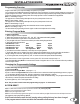
Starter Kill with Bypass Units (Transponder or Passlock) 1 - Cut the Starter Wire between the key and the start and connect to Pins 87a & 30 of the relay. Bypass Unit Ignition Diode 2 - Connect the “Constant” Power wire for the Bypass Unit to Ignition and not “Constant Power. Start Orange 3 - Connect the negative when run input from the bypass unit and pin 86 of the starter kill relay to the Orange Wire of the main unit. ** Diode Isolate if needed.