
Install guide

PAGE 11 INSTALL GUIDE
Step 1 - Connect All Of the Following Wires
Main Connector (6pin)
YELLOW Starter Output - 12volts during start position only.
GREEN Heater/Acc Output - 12volts in the accessory position off during
start and 14volts during run.
RED 12volt 30amp Input - 12volts from ignition harness or battery.
RED 12volt 30amp Input - 12volts from ignition harness or battery.
BLUE Ignition Output - 12volts in the ignition, start and run positions.
WHITE* Selectable Output - Selectable Output for vehicles that may
require a 2nd Ignition, Accessory or Start.
Auxiliary Connector (14pin)
BLACK System Ground Input - Connect to Chassis Ground.
WHITE Park Light Output - Connect to Park Light system.
GRN/WHT Hood Pin Input - Connect to the Hood Pin Safety Switch.
BLUE/WHT Tach Input - Connect to A/C Tach source. (Above 2 volts AC)
PINK Brake Switch Input - Connect to 12volts when the brake pedal
is applied.
for alarm series (2270/4270/4265 series)
GREEN** or Door pin Input - Connect to (-) wire when door open
PURPLE** Door pin Input - Connect to (+) wire when door open
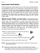
Important!
Never install an AUTOMATIC TRANSMISSION module into a
MANUAL TRANSMISSION vehicle!
*See jumper selector position (page 7).
**Connect only ONE of the door input wires.