CCTV How to Set up a POS Surveillance System using XDVR2POSM/M2 Contents Introduction Benefits Features Devices Required for POS Surveillance System Supported Models.
Introduction Integrated POS surveillance system comprises several components mainly including point-of-sales, cameras and digital video recorders which are capable of recording transaction data. It provides retail managers and shop or company owner with a complete picture of trade activity and also enables emphasizing of suspected or questionable event such as “Sweet hearting discounts” and flagged transactions including “Voids”, “No Sales”and reducing the time spent on reviewing recorded video.
Features • Data synchronization: every sales check’s text information applies to video image • Video Text Overlay: Transaction text message can be displayed on screen and on the video files. You may also choose to hide the data from the screen view. • Exception text:you can predefined 16 set exception event text. For example, all the transactions containing the keyword “VOID” will be marked. • Quick search: you can search the data by product name, price and by channel.
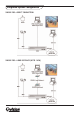
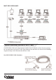
Integrated System Configuration SINGLE POS—DIRECT CONNECTION SINGLE POS—LONG DISTANCE (UP TO 1 KM)
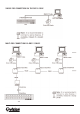
MULTI-POS SURVEILLANCE System Connectivity (with RS232 DB9 Y Cable) The RS232 DB9 Y Cable (see the figure below)is available in both Text Module and Data Converter packages for easy wiring. Please refer to the Y Cable’s figure below for each connector’s use. Also refer to the following diagrams for single / multi- POS connection with the Y Cable.
SINGLE POS CONNECTION VIA THE DB9 Y CABLE MULTI-POS CONNECTION VIA DB9 Y CABLES
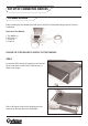
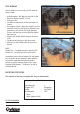
SET UP OF CONNECTED DEVICES Text Module Installation Before attaching the Text Module to the DVR, please check if the Text Module package contains the items listed below. Main Board Text Module: 1. Text Module x1 2. USB Cable x1 3. Screws x4 4. Y-cable x1 FOLLOW THE STEPS BELOW TO INSTALL THE TEXT MODULE. STEP 1 Unscrew the DVR’s cover plate removing screws from the top and side of the lid and remove it from the unit, as shown in the images.
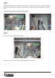
STEP 2 Fasten the Text Module on the location, which is marked as a frame in the right figure. Then connect USB from Socket A (on the Main Board as shown on left) and connect it to Socket B (on the Text Module), as shown on right. Figure: USB Connector A in Socket B in text module STEP 3 Once connected secure down as shown below. Reverse the steps 1 and 2 to assemble the DVR’s partition and the cover.
OSD Setup (Local/Remote) After completing Text Module installation, please carry on the DVR’s OSD setup for activating the text function. To setup the Text Overlay function, enter the OSD setup menu with the correct administrator password, and then select “Text Setup”. Main Menu 1. System Setup 2. Monitor Setup 3. Camera Setup 4. Record Setup 5. Sequence Setup 6. Event Setup 7. Database Setup 8. Configuration 9. Video Export 10. Text Setup 11.
TEXT OVERLAY You can decide to see text overlay in LIVE mode, PB mode or both. • • • • • • • • Available options - OFF, Only Live, Only PB, Live/PB Max lines displayed on OSD : 15 lines 42 bytes per line Text will be blanked out if no more data input in 8 seconds. Line compress feature - When data length in one line exceeds the limit, the DVR will try to eliminate some continuous space to fit the line length limitation. Thus the text format on screen might differ slightly from print-out.
TRIGGER When turned “ON”, those transactions containing “Exception Strings” and meeting “Numerals” conditions will be marked as exceptions in text database and then trigger preset actions such as alarm output, alarm message via e-mail, SMS, etc. Exceptions can also be quickly searched via Text Query in Search menu. EXCEPTION STRING Define Exception String. Max length: 24 bytes. The “Exception String” is case-sensitive. Only exactly matched ones will be marked as exceptions.
PORT SELECTION It is essential to select a port for either the POS/cash register or modem when the text function is set on. Meanwhile, also check whether the device is connected to the port selected. 1. 2. 3. 4. Port Selection Serial Port USB Port-Front USB Port-Rear Top USB Port-Rear Bottom Text NONE NONE NONE TEXT FILTER Text Filter is for filtering control codes out, so that the transactions data read easily. Available options under the item include ASCII, Manual, EPSON (ESC/POS), PartnerTech, etc.
POS ID SETTING The Data Converter’s POS ID should correspond with the cash register’s number, i.e. POS ID 1? Register No.1, POS ID 2? Register No.2, etc. Please refer to the table below for POS ID setting. MODE SETTING Set the mode according to whether the connected device is a transmitter or receiver. Refer to the illustration below for mode setting. BAUD RATE SETTING Refer to the illustration below for baud rate designation. The baud rate is subject to the connected device, i.e.
Example of Data Converter Setting Suppose that there are two POS/ cash registers connecting to a DVR in a POS surveillance system, like the illustration below. Each Data Converter’s POS ID and Mode should be set as follows.
POS Cash Register Setting Please refer to the user manual of the POS/cash register in use for printer-related setting. Text Operation (Local/Remote) Users can easily investigate specific transactions data via Text Module’s text search function, which can be found on the DVR’s Search menu. Press the button SEARCH to enter the Search menu, as shown below. Then move the cursor to the Text Query Page under the item: Search By Text.
SEARCHING CONDITION BY TEXT AVAILABLE OPTIONS • OFF • Specific - Transactions with the specific keyword will be found. • AND - Transactions with the exact two keywords will be found. • OR - Any transaction containing one of the two keywords will be found. • Exception - All triggered exceptions will be listed. NOTE: The search strings mentioned above are case-insensitive - this differs from “Exception String ” setup (see OSD Set-up Exception Text Setup - Exception String).
Then, move the cursor down to “Text Query List” and press ENTER for searching result; see the figure below. • EXC. is the abbreviation of Exception. • The EXC. column will show Exception Strings if searching by “Exception.” • Strings of more than 7 bytes will be abbreviated. excluding: VOID “VOID” NO SALE “NO SALE” BASKETBALL “BASK...” • EXC. will show “-------” when searching by other criteria.
EXPORT • AVI No text overlay support when exporting AVI format • DRV Text overlay is only present in DRV format. Users can use “Local Playback of DVR Remote”, “DVR Player” and CMS to playback DRV file. Text overlay will show when playback DRV file is in full screen mode. NOTE: We recommend using the “ezBurn” function to export DRV file when users have located the wanted video.
Appendix A: Pin Definition of RS232 DB9 Male RS232-A for POS/Cash Register (Half-duplex) Pin 1 2 3 4 5 6 7 8 9 Definition RX GND - RS232-B for DVR (Full-duplex) Pin 1 2 3 4 5 6 7 8 9 Definition RX TX GND RTS CTS -
Appendix B: POS Menu Tree The table below is the POS menu tree. Item Level 1 Level 2 Level 3 Text Setup 1.Text function 2.Text overlay 3.Exception Setup 1.Exception No. <1>~<16> 2.Trigger 3.Exception String Ex: ,,, ,, 4.By Numerals ,,, ,, 4.Input Setup 1.Port Selection , , 2.
Appendix C: List of Supported Models The supported models for pole display and printer are listed below.
Appendix D: ASCII Table