Contents SAFETY INSTRUCTIONS ........................................................................................3 GENERAL INFORMATION .......................................................................................3 1.Source file .............................................................................................................3 2.Reference frame ....................................................................................................4 3.Coordinate ..........................
Safety Instructions 1. Please don’t put your hands between the arms when uArm is moving. 2. Please use the official power supply for safety reasons. 3. Please clear a space for uArm, in case of knocking down anything. General Information General information for the robot arm, and it’s good to know before developing. 1.Source file Source code of Firmware for Swift Pro: https://github.com/uArm-Developer/SwiftProForArduino Source code of ROS for Swift Pro: https://github.
2.
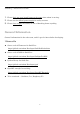
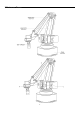
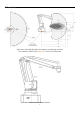
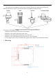
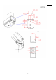
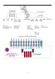
3.Coordinate The picture in the right also shows the dynamic payload range of uArm. Test condition: G2202 F1000; Red point is the Tool Center Point. Detail size of each arm and base.
The origin of base coordinate is in the center of the base. But the tool center point is different for different end-effectors. And we also offer the different commands for different usages.
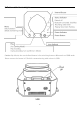
5. Buttons & Indicator Lights Caution: By default, the user defined button is for switching between Bluetooth and USB mode. Please ensure the button is UP while communicating with uArm via USB.
6.
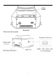
Details of 30P Base Extension 10
Specifications Specifications Weight Degrees of Freedom Repeatability Max. Payload Working Range 50mm~320mm Max. Speed Connector Wireless 100mm/s Micro USB Bluetooth 4.0 Input Voltage Power Adapter DC 12V 2.2kg 4 0.
Integrated Pump Metallic Universal Holder Metallic Gripper OpenMV Camera Integrated Bluetooth Accessories Suction Diameter 5mm~10mm Max. Pressure Max. Lifting Weight Feature Weight Dimension(L*W*H) 33kPa 1000g With feedback 36g 62mm*25mm*15mm Material Holder Diameter Weight Dimension(L*W*H) Material Max. Force Max. Size of Object Max.
Laser Engraving Kit (Only for Pro) Laser Power 500mW Working Voltage/Current Wave Length Weight Dimension(L*W*H) Materials to Engrave 12V/5A 405nm 140g 55mm*33mm*88mm Wood, Plastic, Leather, Feather, Paper, etc. Application Information We would introduce several ways to play with the robot arm in different platform. 1.Send Command over USB Cable Power on the uArm and open the Arduino IDE. And setting the board like the picture below.
Open the serial monitor in the right side of Arduino IDE. After clicking, and you could hear a beep which means the uArm is connected. Set the parameter of serial monitor in the right bottom. If the setting is correct, you would receive the detail information from uArm like the picture below. Now, you are able to send the command to the uArm. Let’s send “G0 X250 Y0 Z130 F10000”.
If uArm finishes the movement, it replies “ok”. Please check the chapter of Protocol (Page 20) in this guide to test more commands.
2.Send Command over Bluetooth Plug in the Bluetooth stick, and press down the button beside the power button. Power on the uArm. When the Bluetooth stick is searching, the blue indicator keeps blink until the wireless connection is built up between stick and uArm. And the blue indicators in both stick and uArm become solid. Open the Arduino IDE. And setting the COM port like the picture below. Please make sure the port you are choosing is the correct port of Bluetooth stick. (Driver of stick: http://www.
Set the parameter of serial monitor in the right bottom like the picture below. Now, you are able to send the command to the uArm. Let’s send “G0 X250 Y0 Z130 F10000”.
If uArm finishes the movement, it replies “ok”. Please check the chapter of Protocol (Page 20) in this guide to test more commands.
3.The 2nd UART Sometimes the 2nd UART is important for our project, for example you want another Arduino to communicate with uArm. During the design, we have had it in mind. There is the 2nd UART in the 30P base extension. All the pins of extension board are connected with the Arduino MEGA 2560 directly so it’s TTL level. And voltage above 5V might burn the IO out. So wiring the UART with the jump wire and also the GND. Then the hardware set up is finished.
How to compile and upload the file? 1. Download the code and extract it to your Arduino libraries folder (normally it’s in C:/Users/ufactory/documents/Arduino/libraries/) 2. Find the file named Marlin.ino in the Marlin folder and open it 3.
4. Select the correct port and type of Arduino board like the picture below 5. Click the upload button to finish the uploading 5.ROS & Python Currently we released the library of Python and ROS. For more information, please check the link below.
Source code of ROS for Swift Pro: https://github.com/uArm-Developer/SwiftproForROS Python library for Swift Pro: https://github.com/uArm-Developer/pyuf 6.OpenMV Demo And also the demo of OpenMV: https://github.com/uArm-Developer/OpenMV-Examples You could find the details steps in quick start guide. 7.Recover from the Wrong Code Sometimes you might want to go back to the official firmware and it’s too complicated to download the Arduino source code and download it.
Protocol 1.Introduction • uArm Gcode is an important part of the uArm software. • Based on the standard gCode protocol, we add a new protocol head in front of the Gcode so that it can be more easily to use and debug. • What’s more, it is designed to be compatible with the standard Gcode. (We offer the code of decode the standard Gcode) 2.Example • Sending command from PC “#25 G0 X180 Y0 Z150 F5000” //move to [180,0,150] with the speed 5000mm/min • Reply from uArm “$25 ok” 3.
GCode Command (v1.2) Description Feedback 1. #n is used for the debug, if you don’t want to use it please remove it directly. (For Example: G2202 N0 V90\n) 2. ‘\n’ is the symbol of line feed. Moving Command (parameters are in underline) #n G0 X100 Y100 Z100 F1000\n Move to XYZ(mm), F is speed(mm/min) $n ok \n or $n Ex \n (refer to Err output) #n G1 X100 Y100 Z100 F1000\n After entering the laser mode $n ok \n or $n Ex \n (refer to Err (M2400 S1), command G1 output) means laser on, G0 means off.
#n M2122 V1\n Report (@9 V0) when stop.
#n M2240 N1 V1\n Set the digital IO output $n ok \n or $n Ex \n (refer to Err output) #n M2241 N1 V1\n Set the digital IO direction (V1 Output; V0 Input;) $n ok \n #n M2245 Vbtname\n Set the name of Bluetooth, 11 letters limited $n ok \n #n M2304 P0\n Please check the Grove modules below #n M2305 P0 N1\n Please check the Grove modules below #n M2306 P0 V1000\n Please check the Grove modules below #n M2307 P0 V1\n Please check the Grove modules below #n M2400 S0\n Set the mode of arm (0:Nor
#n P2206 N0\n Get the angle of number 0 joint $n ok V80\n (0~2) #n P2220\n Get current coordinates $n ok X100 Y100 Z100\n #n P2221\n Get current polar coordinates $n ok S100 R90 H80\n #n P2231\n Get the status of pump $n ok V1\n (0 stop, 1 working, 2 grabbing things) #n P2232\n Get the status of gripper $n ok V1\n (0 stop, 1 working, 2 grabbing things) #n P2233\n Get the status of limited switch $n ok V1 (1 triggered, 0 untriggered) #n P2234\n Get the status of power connection $n ok V1 (
E20 Command not exist E21 Parameter error E22 Address out of range E23 Command buffer full E24 Power unconnected E25 Operation failure Grove modules Grove No. 1 2 3 4 5 Module Chainable RGB LED Button Slide Potentiometer Vibration Motor Light Sensor Commands Description Support Ports Return #n M2304 P3\n Deinit 3, 4, 5 $n ok\n #n M2305 P3 N1 V2\n Init Module 1 in Port 3. V is the number of LEDs chained.
6 Angle Sensor 7 8 Air Quality Sensor Sound Sensor #n M2304 P1\n Deinit 1, 2, 13 $n ok \n #n M2305 P1 N6\n Init Module 6 in Port 1 1, 2, 13 $n ok \n #n M2306 P1 V1000\n Set report interval (ms) 1, 2, 13 @11 P1 N6 V583\n #n M2304 P1\n Deinit 1, 2, 13 $n ok \n #n M2305 P1 N7\n Init Module 7 in Port 1 1, 2, 13 $n ok \n #n M2306 P1 V1000\n Set report interval (ms) 1, 2, 13 @11 P1 N7 V583\n #n M2304 P1\n Deinit 1, 2, 13 $n ok \n #n M2305 P1 N8\n Init Module 8 in Port 1 1, 2, 1
64: clockwise 128:counter clockwise 12 13 14 15 16 Ultrasonic Fan Electromagnet Temperature & Humidity #n M2304 P3\n Deinit 4, 8, 9 $n ok \n #n M2305 P3 N12\n Init Module 12 in Port 3 4, 8, 9 $n ok \n #n M2306 P3 V1000\n Set report interval (ms) 4, 8, 9 #n M2304 P4\n Deinit 4, 8, 9 $n ok \n #n M2305 P4 N13\n Init Module 13 in Port 4 4, 8, 9 $n ok \n #n M2307 P4 V120\n Set Fan speed(0~255) 4, 8, 9 $n ok \n #n M2304 P3\n Deinit 3, 4, 5, 8, 9 $n ok \n #n M2305 P3 N14\n Ini
S: the display string 18 #n M2304 P3\n Deinit 3, 4, 5, 8, 9 $n ok \n #n M2305 P3 N18\n Init Module 18 in Port 3 3, 4, 5, 8, 9 $n ok \n Line Finder @11 P3 N18 V1\n #n M2306 P3 V1000\n 19 Infrared Reflective Sensor EMG Detector 3, 4, 5, 8, 9 0: object detected 1: no detected #n M2304 P3\n Deinit 3, 4, 5, 8, 9 $n ok \n #n M2305 P3 N19\n Init Module 19 in Port 3 3, 4, 5, 8, 9 $n ok \n object @11 P3 N19 V1\n #n M2306 P3 V1000\n 20 Set report interval (ms) Set report interval (ms) 3,
uArm Community UFACTORY Official Forum uArm User Facebook Group uArm Technical Support Release Note Version Note 1.0.0 Setup the document Tony 1.0.1 Update the working range Tony 1.0.2 Add the mounting and detail size of each part Add detail steps of Arduino upload Add the relationship of left/right motor with the upper and lower arm Tony Modify several commands of Gcode Redesign to layout of this guide David 1.0.3 1.0.