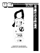
INSTRUCTION MANUAL DL250 1-800-547-5740 • Fax: (503) 643-6322 www.ueitest.com • email: info@ueitest.
Introduction The DL250 Digital Clamp-on is the all-in-one test-tool that's designed to make quick work of HVAC/R service and industrial maintenance. Whether you're measuring flame safeguard current, motor inrush current, run/start capacitors, recording time-stamped temperature highs and lows, or performing general electrical troubleshooting, the DL250 has you covered! It's convenient size, teardrop jaw design and ergonomic controls add speed, comfort and flexibility to your measurement tasks.
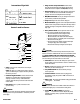
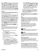
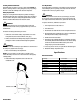
4. Range and Time Stamp Push-button: Switches meter from auto to manual ranging. Also initiates the time stamp function when used in conjunction with MAX/MIN/Recording. International Symbols 5. Hold Push-button: Freezes the value displayed on the digital read-out. This function does not work while recording is in progress. Also turns on back light and work area light. 6. MAX/MIN Push-button: Use to cycle through recorded and present values, and the time stamp function. 7.
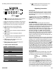
The following describes the indicators displayed by the LCD. 21 22 23 24 25 29. OFL: This symbol appears when the input value exceeds the meters selected range or overall specification. 26 27 Operating Instructions 16 17 18 19 20 28 29 16. BAT this symbol appears when the battery needs replacement. NOTE: A low battery will adversely affect accuracy. 17. AC: Indicates that alternating current/voltage is being measured. 18. Minus (—): I n d i cates the value measured has a negative polarity. 19.
When the “MIN/MAX” button is pressed a second time, the symbol “MAX” appears at the top of the display, while the maximum recorded value is displayed. When the “MIN/MAX” button is pressed a third time, the “MIN” symbol appears at the top of the display, while the minimum recorded values are displayed. If a new high or low value is recorded while you are viewing the “MIN” or “MAX”, that value will be displayed. Pressing the button again will return you to monitoring real-time reading.
The maximum limit for this function is 400 amps AC. Too much current will saturate the ferrous material in the clamp, and adversely affect accuracy. WARNING! DO NOT attempt to take any unknown voltage or current measurements that may be in excess of this meter’s maximum limits. This meter is designed for measuring current and voltage in commercial, residential, and light industrial applications.
The voltage or current applied during resistance measurements could damage some devices. Typically, the voltages applied in the resistance ranges vary from 3 volts in the lowest range to 0.5 volts in the highest range. Current will typically vary from 800 µA at the lowest range to 30 µA at the highest range. To measure resistance: 1. Insert the test leads into the meter, and turn off the power to the circuit under test. Voltage across the circuit, from any source, will cause an erroneous reading. 2.
Measuring Capacitance This meter measures capacitors, such as those used as motor-run-start capacitors, ranging in value from .001 to 10,000 microfarads (µf). WARNING! Capacitors should be completely discharged prior to testing. To measure AC or DC current flow (in amps): 1. Ensure power is off to the circuit to be tested. 2. Insert the test leads into the meter (red to the multifunction port on the right, and black to the common port on the left). 3.
Cleaning and Decontamination Periodically clean your meter’s case using a damp cloth. DO NOT use abrasives, cleaning solvents or strong detergents, as they may damage the finish or affect the reliability of the structural components. Fuse Replacement The DC µA position is protected by a 400 mA fuse. If this fuse blows the meter will display all zeros (example, 00.00 mA) on the LCD when the DC µA function is selected, regardless of input.
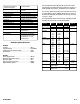
Maximum voltage between any terminal and earth ground Digital display Storage temperature Operating temperature Altitude Relative humidity B a t t e ry type B a t t e ry life M aximum conductor size M aximum jaw opening Size (H x W x L, in mm) Weight (approximate) V i b ration and shock Case protection S a f e tystandards 600 V DC or AC RMS 4000 Count - Updates 4 times per second -4˚ to 140˚F (-20˚ to 60˚) 32˚ to 113˚F (0˚ to 45˚C) = or < 6560’ (2000 M) 0% to 80% at 32˚ to 95˚F (0˚ to 35˚C) 0% to 70% at 95
DL250 Digital Clamp-On Multimeter Limited Warranty The DL250 is warranted to be free from defects in materials and workmanship for a period of three years from the date of purchase. If within the warra n ty period your instrument should become inoperative from such defects, the unit will be repaired or replaced at UEi’s option.