
User Guide

Cleaning and Storage:
WARNING!
To avoid electrical shock or damage to the meter,
do not get water inside the case.
Periodically wipe the case with a damp cloth and
detergent; do not use abrasives or solvents.
If the meter is not to be used for periods of longer than
60 days, remove the battery and store them separately.
4. Check the rotating direction of the rotation
indicator if:
4. If you require the motor to rotate counter
clockwise, you should change connection to
L2 - L1 - L3, the motor should now rotate
counter clockwise.
Battery Replacement:
1. It is necessary to replace battery, when
green lamp is dull.
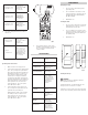
2. Use a screwdriver to unscrew the screws
on the back. Open the case (Fig. 2), take out
the battery and replace with new battery
type (DC 9V battery).
3. Reinstall the case.
Fuse Replacement:
1. It is necessary to replace the fuse when the
lamp indicator R or T show no connection
and change R-S-T is the same.
2. Use a screwdriver to unscrew the screws
on the back. Open the case (Fig. 2), take out
the damaged fuse and replace with a new
fuse (200mA, 250V).
3. Reinstall the case.
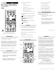
(Fig 1)
(Fig 2)
Open phase check
lamp “R” is not on
Open phase on
terminal where RED
alligator clip
is connected
Open phase check
lamp “S” is not on
Open phase on
terminal where
YELLOW alligator
is connected
Open phase check
lamp “T” is not on
Open phase on
terminal where
BLUE alligator clip
is connected
Lamp of counter
clockwise is lit
Alternate the
connection of two of
the three
alligator clips
Lamp of
clockwise is lit
Phase sequence is
R, S, and T in order
of the power source
terminals where the
RED, YELLOW and
BLUE alligator clips
are connected
Input Voltage: 100V AC up to 600V
AC max
Frequency Range: 45 to 70 Hz
Circuit Structure: All electronic (not
mechanical)
Power Requirement: DC 9V battery
Power Consumption: Consumption current
approx. 14mA of
motor rotation field
of tester. AC power
consumption approx.
7mA per phase
rotation field of
indicator
Installation
Category:
EN61010-1 600V
CAT III
Dimension: 6.02” (L) x 2.83” (W)
x 1.37” (H)
153mm x 72mm x
35mm
Weight: Approx. 212g
including battery
Accessories: Test leads (red,
yellow and blue),
zippered pouch,
instruction manual
Operating motor rotation tester:
1. Make sure there is no voltage present.
2. Connect the test lead to motor input terminal
by L1 - L2 - L3, and press the power button
(Fig 1). The power indicator green lamp is lit.
(If red lamp of clockwise or counter clock
wise is lit before rotating the motor shaft,
it means there is voltage present. Please
stop measuring, take off the test leads and
turn off the external power). If red lamp is lit
while rotating the motor shaft clockwise, it
means 3-phase motor connection to the
power supply by L1 - L2 - L3, the 3-phase
motor will rotate clockwise.
3. Connect the lead to 3-phase motor by L1 -
L2 - L3, and press the power button on. The
power indicator green lamp is lit.
Rotating the motor shaft counter clockwise.
If red lamp of counter clockwise is lit. it
means 3-phase motor connection to the
power supply by L1 - L2 - L3, the 3-phase
motor will rotate clockwise.
SPECIFICATIONS
MAINTENANCE