KM940 Hand-held Combustion Analyser
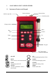
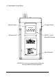
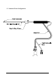
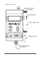
CONTENTS 1. Page No: ANALYSER LAYOUT AND FEATURES............................................................ 4-7 1.1 1.2 1.3 1.4 Instrument features and keypad...........................................................................4 Instrument layout (Rear) .....................................................................................5 Standard Probe Configuration .............................................................................6 Analyser connections ................................
8. MAINTENANCE .......................................................................................................26 8.1 8.2 Emptying and Cleaning the in-line water trap ..................................................26 Changing the particle filter................................................................................26 9. PROBLEM SOLVING ...............................................................................................27 10. ANNUAL RE-CALIBRATION .........................
1. ANALYSER LAYOUT AND FEATURES 1.
1.
1.
1.
2. SAFETY WARNING This analyser extracts combustion gases that may be toxic in relatively low concentrations. These gases are exhausted from the side of the instrument. This instrument must only be used in well ventilated locations. It must only be used by trained and competent persons after due consideration of all the potential hazards.
4. NORMAL START UP SEQUENCE 4.1 Every Time You Use The Analyser BEFORE SWITCH-ON CHECK THAT: the particle filter is not dirty the water trap and probe line are empty of water all hose connections, etc, are properly made the probe is sampling CLEAN AMBIENT air the water trap is correctly fitted and the instrument upright the flue temperature is connected Switch ON the instrument by pressing 4.
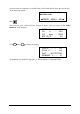
Once the time has reached zero an audible beep will be heard and will show the selected fuel on the following display:NATURAL GAS ∗PRESS -MENU- KEY∗ Press This zeros the toxic sensor and sets Oxygen to 20.9%. The next screen is the MAIN DISPLAY of the analyser:- NETT C O2 % CO ppm EFF (G) % Use and . . . . 0.0 . . . 20.9 . . . 0000 ... 0.0 to change the display. CO2 % . . . . . . . 0.0 FLUE C. . . . . . 0.0 INLT . . . . NOT FITTED AMBIENT C . . . .
4.3 Main Displays The main display can be changed to show either 4 or 8 parameters at one time. Two options are available when 4 parameters are selected. • 4 Page Mode displays 4 lines of data in set format, each page is predefined. • Line scroll mode allows you to customise the display to show the data you require. • 8 Page Mode displays 8 parameters on 4 lines in set format, the bottom two can be changed. Changing between the different modes is detailed in Display Menu Section 5.2.4. 4.3.
4.3.2 Line Scroll Mode Line scroll mode allows you to customise the display. Use the and keys to change the bottom line of the display. Once the correct line is displayed press to confirm and move the line up. Select the next parameter and repeat until all lines display the desired parameters. Change bottom line using and to select and move parameter up Select next parameter. Repeat above until display reads desired data NETT O2 CO CO2 C ... 0.0 % . . . 20.9 ppm . . 0000 % ... 0.0 O2 CO CO2 CO2 % . .
4.4 Sampling the Flue Gas Once the automatic calibration procedure has been completed and the specific fuel has been selected (See SELECT menu) the probe can be inserted into the desired sampling point. It is recommended that the sampling point be located at least two flue diameters downstream of any bend and that the probe tip is in the centre of the flue. With balanced flues and other domestic units the probe should be positioned far enough into the flue so that no air can ‘back flush’ into the probe.
4.6 Regular Checks During Sampling Care must be taken at all times not to exceed the analysers operating specifications, in particular ensure the following :• Do not exceed the maximum temperature of the flue probe. • The analyser internal temperature does not exceed normal operating range, typically 040°C. • DO NOT PLACE THE INSTRUMENT ON A HOT SURFACE. • The water trap is vertical at all times. Water condenses in the probe line and can quickly fill the water trap when the probe is moved.
4.8 Electromagnetic Compatibility The European Council Directive 89/336/EEC requires that electronic equipment does not generate electromagnetic disturbances that exceed defined levels and has an adequate level of immunity to enable it to be operated as intended. The specific standards applicable to this product are detailed in the appendices.
5. MOVING THROUGH THE MENUS 5.1 Basic Operation NETT C O2 % CO ppm EFF (G) % From the MAIN DISPLAY . . . . 0.0 . . . 20.9 . . . 0000 ... 0.0 MAIN MENU Press to access the MAIN MENU 1. SELECT 2. UNITS 3. DISPLAY 4. SETUP MAIN MENU Press and to move cursor up and down 1. SELECT 2. UNITS 3. DISPLAY 4. SETUP MAIN MENU Press to access selected Menu 1. SELECT 2. UNITS 3. DISPLAY 4. SETUP Press to select parameter FUEL O2 Ref SMOKE RESET : LIGHT OIL : OFF : OFF : NO Use and to change setting i.e.
5.2 Menu Options and Settings 5.2.1 Main Menu The MAIN MENU consists of 4 sub menus which are shown below and detailed on the following pages. MAIN MENU 1. SELECT 2. UNITS All sub-menus are accessed using The and 3. DISPLAY 4. SETUP and exited using keys move the cursor within a menu and allow parameters to be changed. TIP Holding down one of these keys scrolls through the data quicker. 5.2.
Calculation of fuel constants are detailed in the Appendix. Fuel constants will have to be calculated before a user fuel can be entered. To enter the user fuel select ‘User Fuel’ and Press USER FUEL K1g : 0.000 K1n : 0.000 K_2 : 0.00 K_3 : 0.00 K_4 : O2r : 00 00 Use and to select the correct value. USER FUEL K1g : 0.350 K_2 : 0.00 K_4 : 0 K1n : 0.000 K_3 : 0.00 O2r : 00 Use to move to the next parameter, repeat above until all parameters are correct. Press to return to SELECT menu.
Selecting YES and will display the following screen. RESET SENSORS O2 % : 20.9 CO & NO = 0 PRESS ENTER MENU TO ESCAPE After pressing the analyser will count down for 5 seconds and then return to the main display. WARNING : The sensors must only be reset if you are sure they have been sampling fresh air for at least 3 minutes. Errors in measurement will occur if the sensors are reset during or just after sampling. 5.2.3 Units Menu TEMP GAS PRESS. EFF.
5.2.4 Display Menu LIGHT : OFF MODE : 8-PAGE CONTRAST : DEFAULT Allows the configuration of the display to be changed. LIGHT : Choose from ON or OFF. MODE : Select 4 or 8 Page Mode or Line Scroll Mode as detailed in section 4.3 Main Displays. CONTRAST :The contrast is set to a DEFAULT value or can be adjusted ↑ LIGHTER or ↓ DARKER. Use the and keys to adjust. 5.2.5. Set-Up Menu The set up menu allows the following parameters to be set / altered. • • • • • • Language.
Once an alarm has been exceeded the display will flash every two minutes warning the user of an alarm state and display the gas concentration. A similar display will be shown during a RECHARGE BATTERY and PUMP OFF alarms. -- -- -- -- -- -- -- -- -- -- -- -- -- -CO ALARM 1010 ppm -- -- -- -- -- -- -- -- -- -- -- -- -- -NO REF: Displayed on the Nitric Oxide unit only. Allows the percentage P in the following calculation to be set. The default value set is 5%.
Header : Allows two lines of 20 characters to be programmed into the analyser. The header appears on the top of the standard printout. This can be used to print your company name and/or phone number. Name/Phone Kane International (44)-1707-375550 ‘LEFT’ USE STORE KEY The screen above shows the standard header setting with the cursor now shown underlining the K in Kane. By using and any letter or number can be chosen. Once the correct character is displayed, use to move right to the next.
6. PRINTING INFORMATION Supplied as accessories for the KANE940 are an infra-red thermal printer or a dot matrix serial printer. Read the manual supplied with each printer prior to operation. Connections to the KANE940 are detailed below : • Infra-red thermal printer - this does not require a cable to transmit the data but uses an infra-red (IR) link similar to a TV remote control. The IR emitter is positioned on the top of the KANE940 and the bottom of the printer.
7. STORING AND RETRIEVING DATA The KANE940 can store up to 100 combustion tests. Once stored, the data can be viewed on the display or downloaded to a PC or printer. 7.1 Storing a ‘Live’ Test While performing a test and viewing the data on the MAIN display access the STORE menu as follows :- Press to access the STORE MENU Mode: STORE MENU MODE : STORE LOCATION : 3 PRESS ‘STORE’ TO LOG Select from the following :• • • Location: STORE - Allows data to be stored in memory.
To print the data press . In the screen shown above locations 1 to 10 will be printed. During printing the following will be shown. PRINT TESTS 1 to 10 PRINTING TEST 1 NOTE While the display above is shown (i.e. the instrument is printing a test) the keypad is disabled. To exit from printing wait until the current test has finished and the display below is shown: PRINT TESTS 1 to 10 PLEASE WAIT MENU TO ESCAPE Press to exit the print routine. The instrument will return to main display 7.
8. MAINTENANCE 8.1 Emptying and Cleaning the In-line Water Trap The in-line water trap should be checked and emptied on a regular basis. Water vapour will condense and gather in the probe line. This may move suddenly to the trap when the probe is moved. Care should be taken at all times. Emptying of the water trap is detailed below :- Carefully remove the end cap from the in-line housing. Dispose of the condensate in a suitable drain, care must be taken as it could be acidic.
9. PROBLEM SOLVING The following is a list of problems that may occur on the instrument through its operating life. If the cause of the fault is not easy to identify then we advise you contact Kane International Service Department or an International Distributor for expert advice.
11. PRODUCT SPECIFICATION Parameter Resolution Accuracy Range Flue Temperature with probe 1.0ºC/F +2.0ºC +0.3% reading 0-600ºC 32-1112ºF Inlet Temperature 0.1ºC/F +1ºC +0.3% reading 0-50ºC/32-122ºF Pressure 0.01 mbar +2% of full scale +150mbar to -150mbar Oxygen 0.1% +0.2% 0-21% Carbon Monoxide 1ppm +20ppm <400ppm +5%<5000ppm +10%>5000ppm 0-10,000ppm 0.01% +5% reading from 0.
Dimensions Weight Handset Probe 1kg 220mm x 55mm x120mm L 420mm x Dia 8mm with stainless steel shaft, type K thermocouple and 3m hose Ambient operating range 0oC to 45oC/ 10% to 90% RH non condensing Power supply (battery charger) Input 110Vac / 220Vac nominal Output: 12Vac off load Battery Life >6 hours from full charge *1 *2 Using dry gases at STP Calculated - 29 -
APPENDICES A - Main Display Parameters The parameters and their meanings are detailed as follows : DATE : Analyser date. See Set-Up menu section 5.2.5 to change. TIME : Analyser time. Use Set-Up menu section 5.2.5 to change. BATTERY : (BAT) Displays the battery level from 0-100%. The analyser will flash RECHARGE BATTERY at less than 10 % of charge. With the charger connected the display shows AC ON.
(Ta) temperature calculation if an INLET probe is not fitted. CO/CO2 R : The CO/CO2 ratio, is the ratio of measured CO divided by calculated CO2. It gives an indication of the following :• • How good a gas sample the instrument is reading. How clean the boiler is running. For example : A new or clean domestic boiler will display a ratio of less than 0.004, a unit in need of cleaning 0.004-0.008 and a unit in need of major overhaul will show greater than 0.008.
B. COMBUSTION EFFICIENCY CALCULATION The efficiency calculation is based upon British Standard BS845.
Calculated data: Tnet Tnet = Net Temperature % CO2 content in flue gas % Dry Flue Gas losses % Wet losses % Unburned carbon loss % Efficiency = Flue Temperature - Inlet Temperature Dry flue gas loss % = 20.9 x K1 x (Tnet) / K2 x (20.9 - O2m) Wet loss % = 9 x H2 + H2O / Qgr x [2488 + 2.1Tf - 4.2 Ti] simplified = [(9 x H2 + H2O) / Qgr] x 2425 x [1 + 0.001 Tnet] Wet loss % = K3(1+0.001xTnet) Where K3 = [(9 x H2 + H2O) / Qgr] x 2425 Net Efficiency % = 100 - dry flue gas losses = 100 - 20.
C. CALCULATION OF FUEL DATA For any fuel not specified by Kane International the net calorific value, gross calorific value and composition should be obtained from the fuel supplier. The following fuel data has been calculated with reference to the efficiency calculation. Example 1: Chemical composition: C H2 H2O Qnet Qg Max CO2 25% 3% 50% 8.35 MJ/kg 9.3 MJ/kg 20.4% K1n = (255 x % carbon in fuel) / Qnet (kJ/Kg) = (255 x 25) / 8350 = 0.
D. ELECTROMAGNETIC COMPATABILITY (CE) STATEMENT This product has been tested for compliance with the following generic standards: EN 61000-6-3 EN 61000-6-1 and is certified to be compliant Specification EC/EMC/KI/KANE940 details the specific test configuration, performance and conditions of use. Please Note: Batteries used in this instrument should be disposed of in accordance with current legislation and local guidelines.