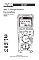
IRT807 1000V AC/DC Digital Insulation Resistance Tester INSTRUCTION MANUAL INSULATION TESTER ENGLISH IRT807 0 0.1 M 1M 10 M 100 M 1G 2G M Apo VDC SELECT MIN/MAX Test Voltage LOCK RANGE A-HOLD F C TEST Temp kHz mV ZERO PI/DAR Hz V V OFF mA SMOOTH 50V 1000V INSULATION 1-800-547-5740 www.ueitest.com • email: info@ueitest.
TABLE OF CONTENTS FEATURES ...................................................................................................................................................5 GENERAL SPECIFICATIONS ...................................................................................................................5 IMPORTANT SAFETY WARNINGS ........................................................................................................6 SYMBOLS ........................................................
IRT807 Insulation resistance tester is designed to help prevent hazards such as electric shock and short-circuits caused when the insulation in electrical devices, parts, and equipment used in plants, buildings, and other settings degrades over long periods of use. FEATURES • Insulation Resistance 2.0GΩ • A-Hold/ Hold • Earth-bond Resistance 20.
IMPORTANT SAFETY WARNINGS WARNING Read entire Safety Notes section regarding potential hazard and proper instructions before using this meter. In this manual the word “WARNING” is used to indicate conditions or actions that may pose physical hazards to the user. The word “CAUTION” is used to indicate conditions or actions that may damage this instrument. WARNING To ensure safe operation and service of the tester, follow these instructions.
SYMBOLS AC Volts DC Volts Warning Fuse Ground Maximum measured value displayed Low Battery AVG Average value displayed Minimum measured value displayed k AC Voltage with “low-pass filter” Auto-ranging Hertz/Frequency Degrees Fahrenheit Degrees Celsius kΩ KiloOhm Ohms/Resistance GΩ GigaOhm DC F SMOOTH 50V 1000V 1000V to 50V (Source Voltage) MΩ MegaOhm RUN TIME Run Time LOCK TEST High Voltage SMOOTH Capacitance Temp Diode test Temperature Continuity Insulation Test mV INS
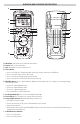
OVERVIEW AND OPERATING INSTRUCTIONS A M INSULATION TESTER IRT807 0 0.1 M 1M 10 M 100 M 1G 2G N B C M Apo VDC D E F SELECT MIN/MAX LOCK RANGE A-HOLD F C TEST Temp kHz V OFF mV ZERO PI/DAR Hz I J K L O P Q V mA SMOOTH 50V 1000V INSULATION G Test Voltage H A. B. C. D. Worklight: Lights work area in dark work environments. Display: High contrast and backlit.
• In Insulation or Earth-bond resistance Test mode, when pressed before the Test Button, the test remains active until you press the lock or test button again to release the lock. J. Range/Test Voltage/Temperature Scale Button: • Press and hold to return to Auto Ranging mode • Press to select desired voltage source in Insulation Resistance mode. • Press to select °F or °C in Temperature mode. K.
Voltage: with 1kHz “low-pass” filter <1000V The IRT807 is equipped with an AC “low-pass” filter. When measuring AC voltage press the Select Button to activate the “low pass” filter function. The meter continues to measure in the selected AC mode, but the signal passes through the filter that blocks any unwanted frequencies above 1kHz. The “low-pass” filter can improve measurement performance on composite sine waves that are typically generated by frequency motor drives and inverters.
DC mV: 1mV to 400mV INSULATION TESTER IRT807 0 0.1 M 1M 10 M 100 M 1G 2G mV M Apo Apo VDC MIN/MAX SELECT Test Voltage LOCK RANGE A-HOLD SELECT F C TEST Temp mV kHz mV ZERO PI/DAR Hz V mA V SMOOTH 50V OFF • Default = • Press x1 = 1000V INSULATION mV Temp mV WARNING • Use CATIII rated Test leads or higher. • Do not attempt to measure more than 400mV DC. • Keep hands below finger guards when measuring high voltage levels.
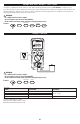
Resistance INSULATION TESTER IRT807 0 0.1 M 1M 10 M 100 M 1G 2G M Apo Apo VDC SELECT Test Voltage SELECT MIN/MAX RANGE LOCK A-HOLD F C TEST Temp kHz V OFF mV ZERO PI/DAR Hz • • • • V mA SMOOTH 50V 1000V INSULATION WARNING • Do not measure resistance on a live circuit. LOCK Features: SELECT A-HOLD Default = Press x1 = Press x2 = Press x3 = Test Voltage MIN/MAX RANGE F C OHMS RANGE 400Ω 4kΩ 40kΩ 400kΩ 4MΩ 40MΩ RESOLUTION 0.1Ω 0.001kΩ 0.01kΩ 0.1kΩ 0.001MΩ 0.01MΩ ACCURACY ±(0.
Diode Test INSULATION TESTER IRT807 IRT807 0 0.1 M 1M 10 M 100 M 1G 2G V M Apo Apo VDC SELECT SELECT MIN/MAX Test Voltage LOCK RANGE A-HOLD F C TEST Temp kHz mV ZERO PI/DAR Hz • • • • V mA V SMOOTH 50V OFF 1000V INSULATION Features: Default = Press x1 = Press x2 = Press x3 = LOCK SELECT MIN/MAX A-HOLD RANGE RESOLUTION ACCURACY OVERLOAD PROTECTION 3V 0.001V ±(2% +1 dgts) 600V CAUTION Discharge all high-voltage capacitors before testing diodes.
mAmps AC/DC INSULATION TESTER IRT807 0 0.
Earth-bond Resistance INSULATION TESTER 0 0.1 M 1M 10 M 100 M IRT807 1G 2G M Apo Apo VDC SELECT SELECT MIN/MAX Test Voltage LOCK RANGE A-HOLD F C TEST Temp kHz mV ZERO PI/DAR Hz V V OFF mA SMOOTH 50V 1000V INSULATION • Default = • Press x1 = ZERO NOTE: Measurements can be adversely affected by impedances of additional operating circuits connected in parallel or transient currents. 1. Insert test leads into the Zero/Ω and Com input ports. 2.
Insulation Resistance/ 1000V/ 500V/ 250V/ 100V/ 50V INSULATION TESTER IRT807 0 0.
Measuring Polarization Index and Dielectric Absorption Ratios INSULATION TESTER IRT807 Polarization Index (PI) is the ratio of the 10-minute insulation resistance to the 1 minute insulation resistance. Dielectric Absorption Ratio (DAR) is the ratio of the 1-minute insulation resistance to the 30-second insulation resistance. PI/DAR Apo SMOOTH 50V Test Voltage LOCK • Default = • Press x1 = WARNING • Insulation tests should only be performed on TEST de-energized circuits.
Testing the Fuse • Turn the rotary selector dial to ZERO/Ω position. • Press and hold the TEST button. If the display shows “FUSE”, the fuse is bad and should be replaced. Please see Fuse Replacement section of this manual. INSULATION TESTER IRT807 V Apo Test Voltage SELECT MIN/MAX RANGE LOCK A-HOLD F C TEST TEST Temp kHz V OFF mV ZERO WARNING: • To avoid electrical shock or injury, remove the test leads and any input signals/voltages before replacing the fuse.
Remote Probe Set 1. Explanation of symbols Symbols Description :Double insulation : See accompanying user manual 2. Intended use and color of the lead Set A) Test probe has the lead wire which is composed of the Nickel Silver, Copper Braid, and PVC Rubber. .One end has a plug and the other end is 4mm (with cap)or 18mm (without cap) probe tip. B) Probe length : 1618 mm ± 5.0 mm C) Wire Color : Black / dimensions : ¢6mm D) Weight : 126g 3. Specification (Dual rating) Voltage (a.c/d.
FCC/IC INFORMATION NOTE: this device complies with part 15 of the fcc rules and can ices-3(a). Operation is subject to the following two conditions: (1) this device may not cause harmful interference, and (2) this device must accept any interference received, including interference that may cause undesired operations. INFORMATION TO THE USER This equipment has been tested and found to comply with the limits for a class b digital device, pursuant to part 15 of the FCC Rules.