
User Guide

8
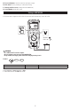
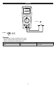
• Short the ends of the test leads together, press the SELECT button and wait until ZERO appears. The meter measures the
test leads resistance, stores the data/results in memory and subtracts it from the reading. The test lead resistance is saved
even after the meter is powered off. If the Probe resistance is >2Ω, the resistance will not be saved.
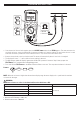
• Connect the test leads to the circuit to be tested. The tester will automatically detect if the circuit is energized.
• The display will show “----” until a valid resistance reading is detected.
• The High Voltage symbol will display if greater than 2V AC or DC is present. If the meter “chirps”when you press the
TEST button, test is corrupted due to voltage being present.
• Press and hold the TEST button on the Meter or Remote Probe to start test. Test stops when the button is released.
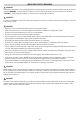
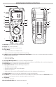
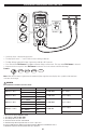
Features:
TEST
SELECT
LOCK
NOTE: When the resistance is higher than the maximum display range the tester displays the > symbol and the maximum
resistance for the range.
WARNING
NEVER test resistance on a live circuit. (Overload Protection: AC 2V rms or DC)
RANGE RESOLUTION ACCURACY
20.00Ω 0.01Ω
±(1.5% +3)
200.0Ω 0.1Ω
2000Ω 1Ω
20.00kΩ 0.01kΩ
1. Accuracies apply from 0 to 100% of range
2. Open Circuit Test Voltage: > 4.0V, < 8V
3. Short Circuit Current: > 200.0 mA
Earth-Bond Resistance <20kΩ
IRT803
OFF
ZERO
ZERO
FUSED
V
Ω
COM
INSULATION
V
1000V
500V
250V
100 V
I
N
S
U
L
A
T
I
O
N
T
E
S
T
E
R
600V
CAT IV 600V
CAT III 1000V
COMPARE
LOCK
PI/DAR
TEST
SELECT
HOLD
Apo
V
IRT 803
Apo
• Default =
• Press x1 =
SELECT
TEST