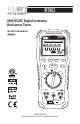
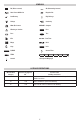
IRT803 600V AC/DC Digital Insulation Resistance Tester INSTRUCTION MANUAL INSULATION TESTER ENGLISH IRT803 0 0.1 M 1M 10 M 100 M 1G 20 G Apo VDC SELECT PI/DAR COMPARE TEST HOLD O ZER 1000V V OFF ZERO LOCK 500V 250V V 0 100 100V OFF V V 500 V 250 V 100 ZERO Ω V INSULATION COM FUSED 600V CAT IV 600V CAT III 1000V 1-800-547-5740 www.ueitest.com email: info@ueitest.
TABLE OF CONTENTS FEATURES ...................................................................................................................................................3 GENERAL SPECIFICATIONS....................................................................................................................3 IMPORTANT SAFETY WARNINGS........................................................................................................4 SYMBOLS .........................................................
IRT803 Insulation resistance tester is designed to help prevent hazards such as electric shock and short-circuits caused when the insulation in electrical devices, parts, and equipment used in plants, buildings, and other settings degrades over long periods of use. FEATURES • Insulation Resistance 20.0GΩ • Compare reading • 600V AC/DC • Rotary dial selector • Earth-bond Resistance 20.
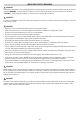
IMPORTANT SAFETY WARNINGS WARNING Read entire Safety Notes section regarding potential hazard and proper instructions before using this meter. In this manual the word “WARNING” is used to indicate conditions or actions that may pose physical hazards to the user. The word “CAUTION” is used to indicate conditions or actions that may damage this instrument. WARNING To ensure safe operation and service of the tester, follow these instructions.
SYMBOLS DC (Direct current) AC (Alternating Current) Auto Power Off Active Negative DC Low Battery High Voltage Voltage Continuity COMPARE Compare Ohms/Resistance Warning or Caution Pass Fuse Test RUN TIME Kilo G Run Time Mega Hold Giga Lock PI/DAR Greater Than ZERO Ground 30 Segment Bargraph CATEGORY DEFINITIONS Measurement Category Short-Circuit (typical) kAa Location in the building installation II < 10 Circuits connected to mains socket outlets and similar points in the MAINS
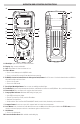
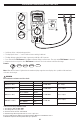
OVERVIEW AND OPERATING INSTRUCTIONS A M INSULATION TESTER IRT803 B C N V Apo J D E F SELECT PI/DAR COMPARE TEST G HOLD 1000V ZERO LOCK O K P L Q 500V 250V V 100V OFF H V INSULATION ZERO Ω COM I FUSED 600V CAT IV 600V CAT III 1000V A. B. C. D. Worklight: Lights work area in dark environments. Display: High contrast and backlit. Apo: Auto power off after 10 minutes of use Select Button: • Press to start battery test in AC/DC V mode.
N. O. P. Q. Test Lead Holders: Used for hands-free testing or storage Kick Stand: For easy viewing of screen when testing. Battery and Fuse Cover: (under protective rubber boot) Serial Number (under kick stand) Voltage <600V AC/DC If the meter detects higher than AC or DC 1.5V, the meter will automatically choose AC or DC.
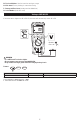
Earth-Bond Resistance <20kΩ INSULATION TESTER IRT803 IRT 803 SELECT V Apo SELECT PI/DAR COMPARE TEST 1000V ZERO TEST LOCK HOLD 500V 250V V 100V OFF • Default = • Press x1 = V INSULATION ZERO Ω COM FUSED 600V CAT IV 600V CAT III 1000V • Short the ends of the test leads together, press the SELECT button and wait until ZERO appears. The meter measures the test leads resistance, stores the data/results in memory and subtracts it from the reading.
Continuity INSULATION TESTER IRT803 IRT803 V Apo Apo SELECT PI/DAR COMPARE TEST 1000V ZERO LOCK HOLD 500V 250V V 100V OFF • Default = ZERO Ω V INSULATION COM FUSED 600V Features: CAT IV 600V CAT III 1000V HOLD WARNING • Do not measure resistance/continuity on a live circuit. • Beeper sounds constant as long as circuit is complete. • Beeper sounds when a short (<40Ω) is detected. RANGE RESOLUTION AUDIBLE THRESHOLD 400.0Ω 0.1Ω Approx.
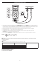
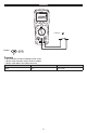
Insulation Resistance/1000V/ 500V/ 250V/ 100V INSULATION TESTER 1000V ZERO IRT803 IRT803 500V 250V V 0 0.1 M 1M 10 M 100 M 1G 20 G 100V OFF Apo Apo M V VDC 1000V ZERO 500V SELECT 250V V PI/DAR 100V OFF COMPARE TEST HOLD 1000V ZERO 500V 250V V 100V OFF 1000V ZERO TEST LOCK • Default = 500V 250V V 100V OFF ZERO Ω V INSULATION COM FUSED 600V CAT IV 600V CAT III 1000V • Set Rotary dial to a desired voltage position.
Polarization Index & Dielectric Absorption Ratios (1000V, 500V, 250V, 100V) INSULATION TESTER ZERO 1000V IRT803 IRT803 500V 0 250V V 0.
Compare Function Use the Compare Function to set “Pass/Fail” compare levels for insulation measurements. Press the Compare Button to select the desired compare value. Choose from the following values: • 100kΩ • 200kΩ • 500kΩ • 1MΩ • 2MΩ • 5MΩ • 10MΩ • 20MΩ • 50MΩ • 100MΩ • 200MΩ • 500MΩ Perform Insulation tests as described in this manual. The PASS symbol will appear on display if the measured value is greater than the selected value. Press and hold the Compare button to stop/disable the Compare function.
Testing the Fuse INSULATION TESTER IRT803 VV Apo Apo TEST SELECT PI/DAR COMPARE LOCK TEST HOLD 1000V ZERO 500V 250V V 100V OFF V INSULATION ZERO Ω COM CAT IV 600V CAT III 1000V FUSED 600V WARNING: To avoid electrical shock or injury, remove the test leads and any input signals/voltages before replacing the fuse. • Turn the rotary selector dial to (ZERO/Ω) position. • Press and hold the Test Button. If the display shows “FUSE” the fuse is bad and should be replaced.
Battery Replacement • AA battery AA battery AA battery AA battery • • • • • When the batteries are too low for safe operation, the Low Battery indicator will display Remove protective rubber boot. Remove battery cover. Replace the batteries (4 AA). Replace the battery cover Replace the protective rubber boot. Fuse Removed protective rubber boot. Removed battery cover. Fuse Replacement AA battery AA battery AA battery AA battery Fuse Removed protective rubber boot. Removed battery cover.
Remote Probe Set 1. Explanation of symbols Symbols Description : Double insulation : See accompanying user manual 2. Intended use and color of the lead Set A) Test probe has the lead wire which is composed of the Nickel Silver, Copper Braid, and PVC Rubber. .One end has a plug and the other end is 4mm (with cap)or 18mm (without cap) probe tip. B) Probe length : 1618 mm ± 5.0 mm C) Wire Color : Black / dimensions : ¢ 6mm D) Weight : 126g 3. Specification (Dual rating) Voltage (a.c/d.
FCC/IC INFORMATION NOTE: this device complies with part 15 of the fcc rules and can ices-3(a). Operation is subject to the following two conditions: (1) this device may not cause harmful interference, and (2) this device must accept any interference received, including interference that may cause undesired operations. INFORMATION TO THE USER This equipment has been tested and found to comply with the limits for a class b digital device, pursuant to part 15 of the FCC Rules.