Test Equipment Depot - 800.517.8431 - 99 Washington Street Melrose, MA 02176 - TestEquipmentDepot.
Introduction Your UEi Megohmeter allows you to predict, prevent and identify insulation failures that can cause appliance failure, stop production, create power problems and even put lives at risk. It quickly tests insulation integrity on motors, power distribution systems and other installed wiring. All insulation has a limited life span and environmental factors such as heat, cold and airborne chemicals can rapidly decrease an insulating material’s predicted life.
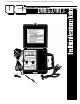
1. Power Switch: Turns instrument power off and on. CAUTION! If any of the above conditions occur, DO NOT attempt to remove the meter leads from the circuit under test. The leads, meter, or circuit under test may have degraded to the point that they no longer provide protection from the voltage and current applied. If any of these erroneous readings are observed, disconnect power immediately. Recheck the physical condition of the test instrument, equipment and all settings and connections.
Operating Instructions Prior to operating your insulation resistance tester, inspect your instrument for: 1. Cracks or damage to the housing. 2. Water intrusion or condensation on the display. Measuring AC Voltage Voltage levels of up to 600 volts AC can be measured with your insulation resistance tester. With test leads installed: 1. Ensure power is on (DMEG3). 2. Place rotary function select switch to the “AC 600 V” position. 3. Damaged test leads. 3.
Note: High precision resistance (continuity) readings can be improved by using the null adjust feature to offset the resistance value of the test leads. To offset this resistance value, follow the instructions through step 4, then adjust the null adjustment knob to indicate zero on the dial or digital display. Your resistance or continuity readings will now display only the resistance in the circuit, not the combined resistance of the leads and the circuit.
Temperature Correction Temperature has a very large impact on your insulation resistance values. When using your meter for predictive or preventive maintenance tasks, the readings must be “temperature corrected” to 20˚C (68˚F). The rule of thumb is, insulation resistance changes by a factor of 2 for every 10 degrees of change in Celsius-scaled temperature.
Preparig Equipment Under Test Isolation is a key factor in properly testing any insulation resistance value. Whether you are testing a motor winding, transformer winding or a cable, you must ensure that the component you are evaluating has no path to ground or other circuits. Contactors and switches must be open and terminal connections must be removed prior to testing.
60-30 Testing The ratio of a reading recorded at 60 seconds compared to that recorded at 30 seconds is one method that gives you a Dielectric Absorption Ratio (DAR). This ratio provides you with the Polarization Index (PI) when you divide the reading observed at the longer term by that of the shorter. The rule of thumb regarding this index (60-second reading divided by 30-second reading) is that it has to be higher than “one” to be acceptable. Anything that has a ratio under 1.
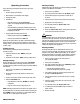
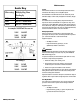
INSULATION RESISTANCE DATA LOG CARD EQUIPMENT MAKE SER. NO. LOCATION PLACED IN SERVICE TEMPERATURE DATE PLOT ADJUSTED READING RELATIVE READING AMBIENT EQUIP. CORRECTION ADJUSTED HUMID I TY FACTOR READING COMMENTS DATE INFINITY 1000 800 600 500 400 300 200 100 80 60 50 40 30 20 10 8 6 5 4 3 2 1 .8 .6 .5 .4 .3 .2 .1 DMEG3/IRT3-MAN P.
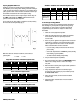
Maintenance Scale Key When using Multiply Meg Ohms 250V Reading By MΩ x .5 = actual value 500V MΩ x 1 = actual value 1000V MΩ x 2 = actual value In example 100 MΩ will be seen as: 250V: 200 MΩ 500V: 100 MΩ 1000V: 50 MΩ Service This instrument contains no user serviceable parts other than the fuse and batteries. All servicing is to be accomplished by UEi. Annual ca l i b ration is recommended and can be conducted by a local calibration facility or at UEi’s factory headquarters in Beaverton, Oregon.
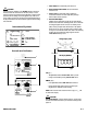
4. Maximum Voltage WARNING! DO NOT attempt this maintenance action with power applied to the instrument either through its test leads or by way of the “Press to Test” button being pressed. To replace the fuse, turn the instrument upside down on a clean, flat surface to expose battery compartment. 1. Remove the battery cover retaining screw. Meet IEC-1010 safety requirements Catagory III 5. Dimensions 6.7 x 6.5 x 3.6 inches (170 x 165 x 92 mm) with housing front cover 6. Dimensions 2.2 lb.
DMEG3/IRT3 Insulation Resistance Tester Limited Warranty The DME G 3 / IRT3 is warranted to be free from defects in materials and workmanship for a period of three years from the date of purchase. If within the warra n ty period your instrument should become inoperative from such defects, the unit will be repaired or replaced at UEi’s option.