
User guide

6
.
P
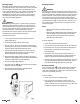
eak Hold Push-Button:
U
sed to capture the highest AC or DC
inductive amp reading.
7. Clamp Lever: Opens and closes current clamp jaw.
8.
DC A Zero: Used to establish the “zero reference” when preparing
to make DC amperage measurements. Magnetic fields in the iron
core of the jaws will be interpreted as a current reading if not
e
lectronically compensated when measuring DC amps.
9. Rotary Function Switch: Used to power the meter on and off, or
to select on of these available measurement functions:
• Inductive AC or DC current using the clamp
• Volts AC or DC at the test lead inputs
• Resistance or continuity at the test lead inputs
10. Off Position: Turns the meter off. Always store your meter in the
off position. If the meter will not be used for a month or more,
remove the batteries.
11.
Display: Communicates function, range, and value information to
the user.
12.
Common Terminal: The black test lead is plugged into this
terminal to supply the ground or “low” reference for voltage and
resistance measurements.
13. Volt / Ohm (Ω) Terminal: The red lead is plugged into this
terminal for AC/DC volts, ohms, and continuity measurements.
14.
Maximum Input Statements: MAX 600V indicates that a
maximum of 600 Volts can be applied between the two terminals or
between earth ground and any terminal for CAT III, 1000 V CAT II.
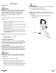
LCD Display Functional Description
1. Peak Hold: Indicates the meter is displaying the maximum inductive
A
C or DC current value recorded.
2. Continuity: Indicates the meter is in the continuity measurement
mode and will sound a tone when measuring resistance below
approximately 40 ohms.
3.
Hold: Indic
ates the value displayed is frozen on screen (the “
D
A
T
A
H
O
LD
” push-button is pressed).
4.
BAT (Low Battery Indicator): This symbol appears when the
battery needs replacement.
Note: A low battery will adversely affect accur
ac
y
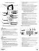
Controls and Indicators
1. Clamp: Wrapped around a single conductor when measuring
inductive AC or DC current. Opens to 1-1/4” (32 mm).
CAUTION!
The clamp uses a high-tension spring to close the jaw. DO NOT allow
fingers or objects to become pinched in the base as jaw closes.
2. Conductor Alignment Marks: Used to aid in the visual
alignment of a conductor when measuring inductive amperage.
Greatest accur
ac
y is achieved when the conductor inside the clamp
is centered at the intersection of these marks.
3.
Hand Guard: Used as a point of reference for the operator’s safety.
WARNING!
Always k
eep your hands and fing
ers behind the hand guards when
measuring current on e
xposed conductors. Contact may r
esult
in serious safety
ground or “low” reference for all measurements.
4.
Data Hold Push-Button: Freezes the value displayed on the
digital read-out.
5.
Range / Worklight - Backlit display Push-Button: Used to
switch from low to high range in the function selected. Note that AC
and DC voltage auto-range from 400 to 1000 volts when more than
400 volts are applied. Push and hold for 5 seconds to activate the
worklight and back light of the display.