
Install Instructions
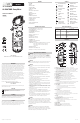

DL469
NCV
CAT III 1000V
MAX
µA
A
CAT Ill
1000V 400A
True RMS
DC Low Amps: < 2000µA
WARNING
• Keep hands below guard when measuring high current levels.
• Do not attempt to measure more than 2000µA DC
Features:
HOLD
DC Low Amps – Test Lead input
Range Resolution Accuracy Overload Protection
400µA 0.1µA
±(1.2% +3 dgts) 2000µA/600V RMS
2000µA 1µA
True RMS: 45Hz to 400Hz
Diode
GOOD DIODE
DL469
NCV
CAT III 1000V
MAX
µA
A
CAT Ill
1000V 400A
True RMS
S / N :
OPEN
LOCK
OPEN
LOCK
Battery Replacement
• When the batteries are too low for safe operation, the Low Battery
indicator will display.
• Rotate latches until Unlock symbols are aligned with arrows. Remove
battery cover.
• Replace the old batteries with 2 new (AAA) batteries.
• Replace the battery cover
• Rotate latches until the lock symbols are aligned with arrows.
OPEN
LOCK
OPEN
LOCK
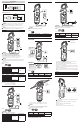
• Center wire in conductor alignment marks for best accuracy.
• Opposing currents cancel (use line-splitter when necessary).
WARNING
• Keep hands below guard when measuring high current levels.
• Do not attempt to measure more than 400A AC
Features:
HOLD
AC Amps: < 400A
Range Resolution Accuracy Overload Protection
40A 0.01A ±(3.0% +10 dgts)
400A/600V RMS
400A 0.1A ±(2.5% +10 dgts)
True RMS Frequency Range: Sine 50Hz to 400Hz
Frequency width: 60Hz to 400Hz: 5% to 95%
Frequency width: 400Hz to 4kHz: 15% to 85%
Single
Conductor
Only
DL469
NCV
CAT III 1000V
MAX
µA
A
CAT Ill
1000V 400A
True RMS
Reverse Bias
Displays "OL"
DL469
NCV
CAT III 1000V
MAX
µA
A
CAT Ill
1000V 400A
True RMS
• Forward voltage drop if forward biased.
• “O.L.” if reverse biased.
Features:
HOLD
BAD DIODE
'0' Both directions
(Shorted)
or
Range Open Circuit V Test Current Overload Protection
4.0V <3.0V DC 1.30mA 600V RMS
• Buzzer sounds at less than 40Ω.
WARNING
• Do not measure resistance on a live circuit.
Features:
HOLD
Open Circuit V Response Time Overload Protection
<1.0V <50ms 600V RMS
Continuity
DL469
NCV
CAT III 1000V
MAX
µA
A
CAT Ill
1000V 400A
True RMS
• Press x1 =
• Default =
DL469
NCV
CAT III 1000V
MAX
µA
A
CAT Ill
1000V 400A
True RMS
AC/DC Voltage: <750V AC/600V DC
• Default =
• Press x1 =
WARNING
• Use CAT III rated Test leads or higher.
• Do not attempt to measure more than 750V AC/600V DC.
• Keep hands below line when measuring high current levels.
• Do not exceed 600 volts AC or DC – RMS at either the common or
multifunction input ports as measured from earth ground.
WARNING
• High Voltage indicator will display and audible alert will sound over 600V
AC/DC and High Voltage indicator will display (without audible alert) over
30V AC/DC.
Select AC or DC Voltage.
Features:
HOLD
DC Volts
Range Resolution Accuracy Overload Protection
400mV 0.1mV
±(0.8% + 5 dgts)
1000V RMS
4V 1mV
40V 10mV
400V 100mV
600V 1V ±(1.0% + 5 dgts)
AC Volts (45Hz to 400Hz)
Range Resolution Accuracy Overload Protection
400mV 0.1mV
±(1.0% + 8 dgts)
1000V RMS
4V 1mV
40V 10mV
400V 100mV
750V 1V ±(1.2% + 8 dgts)
True RMS Frequency Range: Square 50Hz to 170Hz
Sine 50Hz to 400Hz
Bandwidth: Sine = 0.5% error at 1.5kHz (max)
Square = 0.5% error at 0.1kHz (max)
Triangle = 0.5% error at 1.2kHz (max)
Range Resolution Accuracy Overload Protection
400Ω 0.1Ω
±(1.0% +5 dgts)
600V RMS
4kΩ 1Ω
40kΩ 10Ω
400kΩ 100Ω
4MΩ 0.001MΩ
40MΩ 0.01MΩ ±(1.5% +5 dgts)
Resistance: <40MΩ
Features:
HOLD
WARNING
• Do not measure resistance on a live circuit.
DL469
NCV
CAT III 1000V
MAX
µA
A
CAT Ill
1000V 400A
True RMS
M
• Default =
• Press x1 =
• Select NCV and move the tip of the clamp meter near the voltage source.
Both an Audible and Visual alert will indicate voltage.
• Non-Contact Voltage Detection is used to detect power with the sensor
located at the tip of the clamp head
• Do not use non-contact voltage detector to determine if there is current in
the wire. Detection operation could be affected by socket design, insulation
thickness, type and other factors.
• Voltage indicator light may also light when voltage is present on the meter’s
input jack or from external interference sources such as motors, flashlights,
etc.
Non-Contact Voltage Measurement
DL469
NCV
CAT III 1000V
MAX
µA
A
CAT Ill
1000V 400A
True RMS
On Voltage
Approx. 25V AC
NCV Sensor
located in tip
Test Lead Notes
Cat IV and CAT III Measurement Locations
• Ensure the test lead shield is pressed firmly in place. Failure to use the CAT
IV shield increases arc-flash risk.
CAT II Measurement Locations
• CAT IV shields may be removed for CAT II locations. This will allow testing
on recessed conductors such as standard wall outlets. Take care not to lose
the shields.
WARNING: Test Lead category protections apply only to test leads and
should not be confused with the meter’s specific CAT rating. Observe the
maximum category protection indicated on the meter the test leads are
plugged into.
CAUTION: If the test leads need to be replaced, you must use a new one
which should meet EN 61010-031 standard, rated CATIII 1000V or better.
4mm
CATIV
600V
CATIV
600V
CATII
1000V
18mm
4mm
CATIV
600V
CATIV
600V
CATII
1000V
18mm
Open Diode
Displays "OL"
Both directions
Forward Bias
Displays approx.
voltage drop
A
A
µ