INSTRUCTION MANUAL 1-800-547-5740 • Fax: (503) 643-6322 www.ueitest.com • email: info@ueitest.
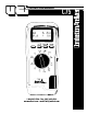
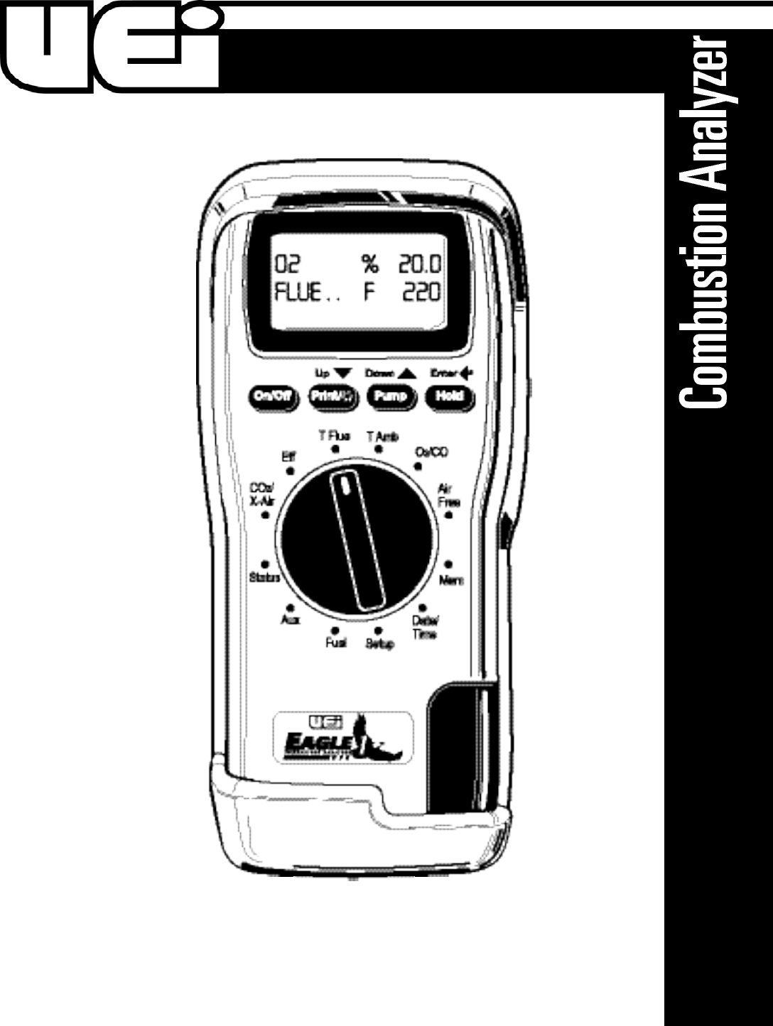
Introduction Controls and Indicators The goal of combustion analysis is to maximize the energy obtained from a fuel while minimizing the risk of toxic gases and additional maintenance needs. Using an electronic combustion analyzer will give you the needed values quickly for proper equipment set-up and tuning of combustion equipment. Common parameters to measure are CO2 and efficiency. This analyzer measures O2, CO and flue temperature, and then calculates those.
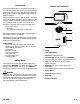
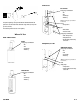
Battery Replacement This meter has been designed for use with both alkaline and rechargeable Nickel Metal Hydride (NiMH) batteries. No other types are recommended. The analyzer is supplied with 4 “AA” size alkaline batteries. These should be installed into the instrument as shown below (Fig 1) and indicated on the back of the unit. Probe Configuration Type K-Thermometer plug Stainless steel shaft Depth stop cone 9 foot neoprene hose Fit probe connector to end of tube using barbed end.
Analyzer Connections Flue (Tf) temperature socket Mains adapter socket Flue gas inlet Selecting Fuel To set the fuel simply rotate the selector to “FUEL” then press the “UP” or “DOWN” arrows to scroll through the choices. When the correct fuel is displayed on the bottom line press “ENTER” to choose this fuel. Symbol Legend Symbol Description Notes Efficiency (gross) Calculated percentage efficiency based on net temperature, O2 value and fuel selected.
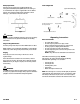
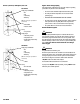
Furnaces: 80% 80% Furnace Verify proper combustion: • O2 • CO • Stack temp • Efficiency (Note: The following may require additional test instruments) The probe depth stop cone provided with the instrument allows the probe to be used in holes whose diameters range from 1/4 to 4/5 inch (6 mm to 21 mm). Set Up • Gas pressure The standard probe is rated at 1112˚F (600˚C).
Furnaces (CONTINUED): Atmospheric, Gas & Oil Gas Furnace Verify proper combustion: • O2 • CO • Stack temp • Efficiency (Note: The following may require additional test instruments) Test • Limit switch • Pressure switch Regular Checks During Sampling Care must be taken at all times not to exceed the analyzer’s operating specifications.
Moving Through the Menu The options in the menu system are in the following sequence by pressing the down arrow: Note: The menu choices are selected using the text printed on the case above the function keys. The three keys are “ “ increases, “ “ decrease and “ “ enter. Set Time 1. Press “ENTER”. 2. Use the up and down keys to select the correct time. 3. Press “ENTER” to move to the next digit. Note: Time is displayed in military format, example 7:00 pm is 19:00. Date 1. Press “ENTER”. 2.
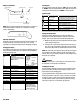
Printing A Test During combustion tests the analyzer can print data on request. With the analyzer showing the data, briefly press the “PRINT“ button until “PRINTING” is displayed. The standard printout is: NOTE: Printouts of stored readings will also include the TEST NO. below the header. SMOKE area on printout is for adding data from manual test.
If condensate spills onto the skin or clothing, clean off immediately using fresh water, seek medical advice if problems occur. Ensure plug is replaced before performing combustion tests. Changing the Particle Filter This is a very important part of the analyzer and should be changed regularly. It prevents dust and dirt particles from entering the pump and sensors that will cause damage. The filter MUST be changed when it appears discolored.
Efficiency Calculation: Known Data - Fuel: Qgr = Gross Calorific Value (kJ/kg) Qnet = Net Calorific Value (kJ/kg) K1 = Constant based on Gross or net Calorific Value K1g = (255 x % Carbon in fuel)/Qgr K1n = (255 x % Carbon in fuel)/Qnet K2 = % max theoretical CO2 (dry basis) K3 = % Wet loss H2 = % Hydrogen H2O = % Water Measured Data: Calculated Data: Tnet Tf = Flue Temperature Ti = Inlet Temperature O2m = % Oxygen in flue gas O2r = Oxygen reference % Tnet = Net Temperature % CO2 content in flue gas % Dr
Troubleshooting The following is a list of problems that may occur on the instrument through its operating life. If the cause of the fault is not easy to identify then we advise you to contact UEi Technical Support line at (800) 547-5740.
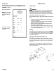
Specifications Parameter Temp Measurement Flue temperature Range Resolution Accuracy 1.0˚ F/C Inlet temperature 1˚ F/C Temp (Nett)*2 1.0˚ F/C ±5˚F (2.0˚C) ±0.3% reading ±1˚ F/C ±0.3% reading ±5˚F (2˚C) ±0.3% reading 32 - 1112˚F 0 - 600˚C 32 - 212˚F 0 - 100˚C 32 - 1112˚F 0 - 600˚C Gas Measurement Oxygen *Carbon Monoxide 0.1% 1 ppm Carbon Dioxide*2 Efficiency*2 Excess Air*2 Pre-programmed fuels Dimensions Weight Handset Probe Ambient operating Battery life range AC adapter (optional) ±0.
C75 Combustion Analyzer Limited Warranty The C75 is warranted to be free from defects in materials and workmanship for a period of three years (two years on sensors) from the date of purchase. If within the warra n ty period your instrument should become inoperative from such defects, the unit will be repaired or replaced at UEi’s option.